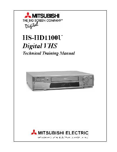
Service Manuals, User Guides, Schematic Diagrams or docs for : MITSUBISHI Proj TV HS-HD1100U_Training_Manual hs_hd1100u_training_manual_438
<< Back | HomeMost service manuals and schematics are PDF files, so You will need Adobre Acrobat Reader to view : Acrobat Download Some of the files are DjVu format. Readers and resources available here : DjVu Resources
For the compressed files, most common are zip and rar. Please, extract files with Your favorite compression software ( WinZip, WinRAR ... ) before viewing. If a document has multiple parts, You should download all, before extracting.
Good luck. Repair on Your own risk. Make sure You know what You are doing.
Image preview - the first page of the document

>> Download hs_hd1100u_training_manual_438 documenatation <<
Text preview - extract from the document
HS-HD1100U
Digital VHS
Technical Training Manual


       MITSUBISHI ELECTRIC
       MITSUBISHI DIGITAL ELECTRONICS AMERICA, INC.
                                   HS-HD11OOU
                       Digital VCR Technical Training Manual
                                 Table of Contents


Section 1 ... Features & D-VHS Basics
 Features ............................................................................................................ 1-1
 Interconnect Block Diagram ............................................................................... 1-2
 Digital Tape ....................................................................................................... 1-2
 Recording and Playback .................................................................................... 1-3
 Digital Heads Configuration ............................................................................... 1-3
 Overall Head Configuration ................................................................................ 1-4
 Speed Search ................................................................................................... 1-5

Section 2 ... Test Point & Service Modes
 PCBs Location .................................................................................................. 2-1
 Service Adjustments .......................................................................................... 2-2
     Test Points.................................................................................................. 2-2
 Service Codes and Procedures ......................................................................... 2-4
     Service Adjustment Mode ........................................................................... 2-4
     EE Mode with the Deck Removed .............................................................. 2-4
     Deck Operational Check ............................................................................ 2-4
 Additional Miscellaneous Service Information ..................................................... 2-4

Section 3 ... Power Supply
 Regulator ........................................................................................................... 3-1
     Oscillation .................................................................................................. 3-2
     Regulation .................................................................................................. 3-2
     Over Current Prevention ............................................................................. 3-2
 Standby DC Supplies ........................................................................................ 3-3
 Switched Supplies ............................................................................................. 3-4
 Protection Circuit ............................................................................................... 3-4
 Troubleshooting ................................................................................................. 3-5

Section 4 ... Digital Circuitry
 Overall Digital Signal Path .................................................................................. 4-1
 Digital Head Amplifiers ...................................................................................... 4-3
 PCB-HA Control Circuitry ................................................................................... 4-3
 Digital Control Circuitry ...................................................................................... 4-3
 Digital Circuitry Troubleshooting ......................................................................... 4-4
      DC Supplies ............................................................................................... 4-5
      Input/Output Signals .................................................................................... 4-6
      Control Signals ........................................................................................... 4-6
      Timing Signals ............................................................................................ 4-6
      No Digital Playback .................................................................................... 4-6
      No Digital Record ....................................................................................... 4-7

                                                          1
Section 5 ... Analog Circuitry
 Analog Video Record/Playback ......................................................................... 5-1
 Sound Signal Path ............................................................................................. 5-2
 Analog Control Circuitry ..................................................................................... 5-3
     Input Command Circuitry ............................................................................ 5-4
 Analog Circuitry Troubleshooting ........................................................................ 5-4


                                                       2
                              Section 1
                       Features & D-VHS Basics


Digital-VCR (D-VCR) model HS-HD1100U is simi-                VCR, using external video and audio inputs/outputs
lar to the HS-HD2000U. Both Digital VCRs are                 or the RF Inputs/Outputs.
capable of conventional analog, digital High Defini-
tion (HD) and Standard Definition (SD) Recording/            To Record/Playback High Definition (HD) or Stan-
Playback.                                                    dard Definition (SD) digital signals, the VCR must
                                                             be connected to a TV, or Set Top Box, with a DTV
Table 1-1 shows the main feature differences of the          Tuner, Demodulator and HD Decoder, and must fea-
two VCRs. The main differences are the HS-                   ture IEEE-1394 compatibility. All V19 and V21
HD1100U does not feature S-VHS Record/Playback               chassis models are compatible, and Mitsubishi HD
and does not feature Cable Box and DBS Satellite             Ready models with the "Promise Module" installed
control.                                                     are compatible.

For analog Record/Playback the interconnections be-          For digital Record/Playback, the only cable connec-
tween the VCR and TV are the same as with any                tion between the D-VCR and the TV is a four wire
                                                             1394 cable.
                  Feature                     HS-HD1100U      HS-HD2000U
                  Language                      English         English
                  Cable Converter Control         No              Yes
                  DBS Satellite Control           No              Yes
                  RentalXpress                    Yes             Yes
                  Comb Filter                     Yes            3DYC
                  VHS Record/Playback             Yes             Yes
                  S-VHS Record/Playback           No              Yes
                  VHS Hi Fi                       Yes             Yes
                  HD & SD Record/Playback         yes             Yes
                    Table 1-1: HS-HD1100U/HS-HD2000U Feature Comparison

                                                       1-1
      Interconnect Block Diagram                             The MPEG-TS signal is the compressed HD Trans-
Figure 1-1 illustrates a Basic Block Diagram of the          port Data Stream and is directed over the 1394 cable
TV and D-VCR and the interconnections between                to the D-VCR. The D-VHS circuitry processes the
the two units.                                               MPEG-TS signal, converting it to an FM signal and
                                                             directing it to the Digital Heads on the Video Drum.
The signal source for conventional VHS analog re-
cording can be the Monitor Output Jack on the TV,                              Digital Tape
or the Conventional Tuner in the HS-HD1100U.                 High density D-VHS tape must be used to Record
When playing back a VHS analog recording the sig-            and Playback HD and SD digital signals. There are
nal from the VCR is directed to a Video Input Jack           two digital recording modes, HS and STD. HS is
on the TV.                                                   used to record HD broadcast signals. The HS mode
                                                             tape speed is the same as the VHS SP mode. The
To record an HD or SD digital signal the source must         STD mode is used to record SD broadcast signals,
from a DTV Tuner, Demodulator and MPEG De-                   and the tape speed is
◦ Jabse Service Manual Search 2024 ◦ Jabse Pravopis ◦ onTap.bg ◦ Other service manual resources online : Fixya ◦ eServiceinfo