Service Manuals, User Guides, Schematic Diagrams or docs for : MITSUBISHI Proj TV VZ9_Chassis VZ9_Chassis
<< Back | HomeMost service manuals and schematics are PDF files, so You will need Adobre Acrobat Reader to view : Acrobat Download Some of the files are DjVu format. Readers and resources available here : DjVu Resources
For the compressed files, most common are zip and rar. Please, extract files with Your favorite compression software ( WinZip, WinRAR ... ) before viewing. If a document has multiple parts, You should download all, before extracting.
Good luck. Repair on Your own risk. Make sure You know what You are doing.
Image preview - the first page of the document

>> Download VZ9_Chassis documenatation <<
Text preview - extract from the document
                                                                         VZ9 Chassis Technical Training


                                        Chapter 1
                                      Power Supply


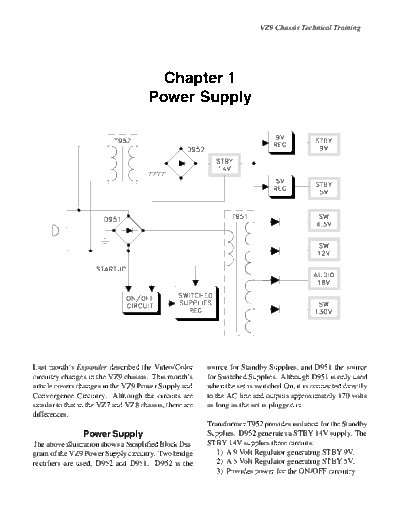
Last month's Expander described the Video/Color         source for Standby Supplies, and D951 the source
circuitry changes in the VZ9 chassis. This month's      for Switched Supplies. Although D951 is only used
article covers changes in the VZ9 Power Supply and      when the set is switched On, it is connected directly
Convergence Circuitry. Although the circuits are        to the AC line and outputs approximately 170 volts
similar to that in the VZ7 and VZ8 chassis, there are   as long as the set is plugged in.
differences.
                                                        Transformer T952 provides isolation for the Standby
                Power Supply                            Supplies. D952 generates a STBY 14V supply. The
The above illustration shows a Simplified Block Dia-    STBY 14V supplies three circuits:
gram of the VZ9 Power Supply circuitry. Two bridge         1) A 9 Volt Regulator generating STBY 9V.
rectifiers are used, D952 and D951. D952 is the            2) A 5 Volt Regulator generating STBY 5V.
                                                           3) Provides power for the ON/OFF circuitry.
                                                                              VZ9 Chassis Technical Training


The ON/OFF circuitry also receives Start Up volt-            ON/OFF Circuitry
age from the half wave rectification at one of the AC        As stated earlier, the Start Up voltage source is from
inputs of D951. When the set is switched On, the             one AC input of D951. The voltage is directed
ON/OFF circuitry directs the Start Up voltage to a           through R964 to the collector of Q9A79 and the
Switch Mode Regulator, the source of all Switched            collector of the Photo Transistor in PC952. When
Supplies.                                                    the set is switched On, the P-ON1 line from the Con-
                                                             trol Circuitry goes High. The High drives Q980 into
T951 provides isolation for the Switched Supplies            conduction, lighting the LED in PC952. Light from
generated at the secondary windings of the trans-            the LED:
former. Four Switched supplies are generated by                 1) Turns the Photo Transistor On.
rectifying the signals from the secondary windings:             2) Which turns ON Q9A79.
◦ Jabse Service Manual Search 2024 ◦ Jabse Pravopis ◦ onTap.bg ◦ Other service manual resources online : Fixya ◦ eServiceinfo