Service Manuals, User Guides, Schematic Diagrams or docs for : NEC _dataSheets uPD372_Floppy_Disk_Controller_Addendum_Apr77
<< Back | HomeMost service manuals and schematics are PDF files, so You will need Adobre Acrobat Reader to view : Acrobat Download Some of the files are DjVu format. Readers and resources available here : DjVu Resources
For the compressed files, most common are zip and rar. Please, extract files with Your favorite compression software ( WinZip, WinRAR ... ) before viewing. If a document has multiple parts, You should download all, before extracting.
Good luck. Repair on Your own risk. Make sure You know what You are doing.
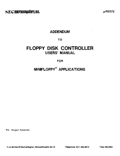
Image preview - the first page of the document

>> Download uPD372_Floppy_Disk_Controller_Addendum_Apr77 documenatation <<
Text preview - extract from the document
~EC     IlcrOcOlputers, Inc.                                                             }LPD372


                                            ADDENDUM

                                                     TO


                    FLOPPY DISK CONTROLLER
                                        USERS' MANUAL

                                                     FOR


                            MINIFLOPPyTM APPLICATIONS


TM - Shugart Associates


 Five Militia Drive/Lexington, Massachusetts 02173         Telephone (617) 862-6410   Telex 92-3434
           TABLE OF CONTENTS


INTRODUCTION                    2


MINIFLOPPY INTERFACE SIGNALS    3


RECORDING FORMAT                6


DATA CONDITIONER                9


SAMPLE CONTROLLER DESIGN       11


       Hardware                11

       Software                13


                       1
                     INTRODUCTION


     The discussion and design shown in this Addendum is
dedicated to the MinifloppyTM Diskette Storage Drive. This
drive is somewhat different, both electrically and mechanically,
from the standard floppy disk drives found throughout the
industry.   The Minifloppy is smaller, less expensive, and is
based upon the same floppy disk drive technology as the standard
floppy.   However, its data transfer rate is half as fast and its
total data storage capacity is approximately one-third.

      This design uses a single uPD372 Floppy Disk Controller to
control a pair of Minifloppies. The interface to the floppies
has been configured so as to allow overlap-seeks to be
programmed.   If only a single drive is used or if overlap-seeks
are not required, then two or three logic Ie's may be removed
from this design. The controller's architecture remains the same
as in the standard floppy design shown in the uPD372 Users'
Manual.

     Before proceeding into the design of this controller, the
uPD372 Users' Manual should be read. All the basic concepts and
characteristics of the uPD372 are explained in this document, and
it will be assumed that the reader is familiar with them. For
clarity in this document the uPD372 Users' Manual will be
referred to as Users' Manual and this document referred to as the
Addendum.


TM -- Shugart Associates


                                 2
              MINIFLOPPY INTERFACE SIGNALS


     There are several signals which have been deleted in the
Minifloppy as well as several new signals.  These are summarized
below:

     Deleted Signals                     New Signals
     (Used only on Standard Floppy)

     Head Load                           Index/Sector

     write Fault                         Drive Select I

     write Fault Reset                   Drive Select 2

     Low Current                         Drive Select 3

     Sector                              Motor ON

     Index

     Ready


     The Head Load signal has been deleted in the Minifloppy.
The head is loaded concurrently with the Motor ON signal. write
Fault and Write Fault Reset which were tests of the Floppy's
status prior to attempting to write a diskette, have both been
eliminated. Many standard floppies (IBM compatible) have a Low
Current signal which allows the write current in the recording
head to be decreased on tracks 44-76 -- this signal has been
eliminated.  If a hard sector recording format is used, the
standard floppies provided separate signal outputs for both
Sector and Index. The Minifloppy requires that the user separate
these signals (this is usually done with a one-shot circuit).
The READY command in the standard floppy indicated to the
controller that a diskette had been inserted, the door was
closed, and that the diskette was spinning; this signal has also
been eliminated.

     Three separate device select lines are provided on the
Minifloppy and the appropriate one is selected by the use of
hardware straps in the drive. This allows a maximum of three
drives to be selected without additional decoding hardware.  The
Minifloppy uses a dc motor for rotating the diskette, a separate
signal called MOTOR ON is used for turning the motor on.  In
order to increase the longevity of the motor, software has been
incorporated in the controller so that two seconds after the last
program instruction, the motor is shut off.

     The following figure shows a typical interface connection
between the controller and the Minifloppy.


                                3
                               FLAT RIBBON OR
                                 TWISTED PAIR

                                    MAX 10 FEET
          CONTROLLER                                               MINI FLOPPY
                                                                         Jl
                                                                              7-
                     7
                                    INDEX/SECTOR             8                9~
                     9    8
                                    DRIVE SELECT 1           10               11~
                     II   10
                                    DRIVE SELECT 2           12               13~

                     13 12
                                    DRIVE SELECT 3           14               15~
                     15 14
                                    MOTOR ON                 16               17~
                     17 16
                                    DIRECTION SELECT         18               19-
◦ Jabse Service Manual Search 2024 ◦ Jabse Pravopis ◦ onTap.bg ◦ Other service manual resources online : Fixya ◦ eServiceinfo