Service Manuals, User Guides, Schematic Diagrams or docs for : NIKKO Audio Gamma V hfe_nikko_gamma_v_service

<< Back | Home

Most service manuals and schematics are PDF files, so You will need Adobre Acrobat Reader to view : Acrobat Download Some of the files are DjVu format. Readers and resources available here : DjVu Resources
For the compressed files, most common are zip and rar. Please, extract files with Your favorite compression software ( WinZip, WinRAR ... ) before viewing. If a document has multiple parts, You should download all, before extracting.
Good luck. Repair on Your own risk. Make sure You know what You are doing.


Image preview - the first page of the document
hfe_nikko_gamma_v_service


>> Download hfe_nikko_gamma_v_service documenatation <<

Text preview - extract from the document
ALIGNMENT
TEST EQUIPMENT                                                     GENERAL ALIGNMENT INSTRUCTION
Allow a minimum of 10 minutes warm-up for test equip-              Always observe response curve on oscilloscope during
ment and the tuner to be tested.                                   alignment procedure:
Maintain rated line voltage.                                       1.  Do not apply signal from FM or AM stations.
FM Signal Generator (FM SG)                                            Apply signal from generator only.
Oscillascope                                                       2. Use of excessive signal from FM SG or AM SG can
AC Voltmeter                                                           cause overloading of the tuner circuits. To properly
Distortion Meter                                                       align the tuner, adjust FM SG or AM SG output
MPX Signal Generator (MPX SG)                                          level control so that response curve on oscilloscope is
Frequency Counter                                                      not distorted.
AM Sweep Generator (AM SG)
DC Voltmeter

FM SECTION

                                                                                                                  1 DISTORTION 1


                                                                                                         L-J
                                     5.12   MHz ADJ; 76 kHz ADJ                                                        AC VOLT-
                                                                                                                        METER


                                                                                                                                     1
   I MPX    SIGNAL GENERATOR I                                                                           _
                                                                                                         -
                                                                                                             _-
                                                                                                             _-        INPUT
      OUTPU T
                             I
                                                                                                                  I
                                                                                                                      OSCILLOSCOPE

     FM SIGNAL GENERATOR
                                  STANDARD
                                   DUMMY
                                                              GAMMA     V
  1 IZEXT   MOD INPUT
                                                                                       L    --_
                                                                                            ___
                                                                                            ___
                                                                                                    --
                                                                                                    --
                                                                                            --_
                                 TO FM ANTENNA TERMINALS                    TO OUTPUT TRERMINAl_S


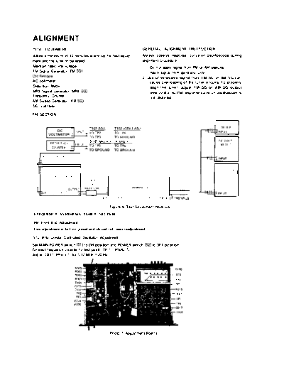
                                                  Figure 6. Test Equipment Hook-up
FREQUENCY SYNTHESIS TUNER SECTION

FM Front End Adjustment
This adjustment is factory preset and should not need readjustment.

5.12 MHz Crystal Controlled Oscillator Adjustment.
Set MAIN POWER switch (Sl I to ON position and POWER switch (S2) to OFF position.
Connect frequency counter to test point "TP 1" (Photo 7).
Adjust C917 (Photo 7) for 5.12 MHz * 20 Hz.


                                                                                       -TF5

                                                                                       - TF4
                                                                                       - TP5
                                                                                       -R316
                                                                                       - R315
                                                                                       -TPl
                                                                                       5-TP4
                                                                                        $-c917


                                                 Photo 7. Adjustment Points


◦ Jabse Service Manual Search 2024 ◦ Jabse PravopisonTap.bg ◦ Other service manual resources online : FixyaeServiceinfo