Service Manuals, User Guides, Schematic Diagrams or docs for : ONKYO Audio FR-155 Onkyo+FR-155
<< Back | HomeMost service manuals and schematics are PDF files, so You will need Adobre Acrobat Reader to view : Acrobat Download Some of the files are DjVu format. Readers and resources available here : DjVu Resources
For the compressed files, most common are zip and rar. Please, extract files with Your favorite compression software ( WinZip, WinRAR ... ) before viewing. If a document has multiple parts, You should download all, before extracting.
Good luck. Repair on Your own risk. Make sure You know what You are doing.
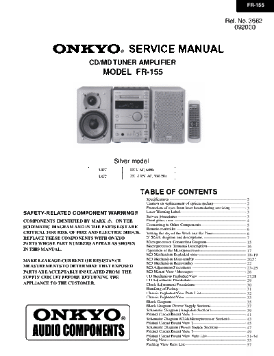
Image preview - the first page of the document

>> Download Onkyo+FR-155 documenatation <<
Text preview - extract from the document
                                                                                                                      FR-155


                                                                                                       Ref. No. 3662
                                                                                                          092000


                         CD/MD TUNER AMPLIFIER
                              MODEL FR-155


                                   Silver model
                             UDT        120V AC, 60Hz
                             UGT        220 -230V AC, 50/60Hz


                                             TABLE OF CONTENTS
                                                 Specifications -----------------------------------------------------------
                                                                                                                         2
                                                 Caution on replacement of optical pickup ---------------------------    2
                                                 Protection of eyes from laser beam during servicing ---------------     3
SAFETY-RELATED COMPONENT WARNING!!               Laser Warning Label---------------------------------------------------- 3
                                                 Service procedures -----------------------------------------------------3
COMPONENTS IDENTIFIED BY MARK      ON THE        Front panel view --------------------------------------------------------
                                                                                                                         4
                                                 Connecting to Other Components------------------------------------      5
SCHEMATIC DIAGRAM AND IN THE PARTS LIST ARE      Remote controller -------------------------------------------------------
                                                                                                                         6
CRITICAL FOR RISK OF FIRE AND ELECTRIC SHOCK.    Setting the day of the Week and the Time----------------------------    6
REPLACE THESE COMPONENTS WITH ONKYO              IC Block diagram and descriptions -----------------------------------   7
                                                 Microprocessor Connection Diagram---------------------------------      15
PARTS WHOSE PART NUMBERS APPEAR AS SHOWN         Microprocessor Terminal Description--------------------------------     16
IN THIS MANUAL.                                  Operation of the Microprocessor--------------------------------------   17
                                                 MD Mechanism Exploded view-------------------------------------18~19
MAKE LEAKAGE-CURRENT OR RESISTANCE               MD Mechanism Disassembly ----------------------------------------       20,21
                                                 MD Mechanism Reassembly ----------------------------------------22
MEASUREMENTS TO DETERMINE THAT EXPOSED           MD Adjustment Procedures ------------------------------------------     23~25
PARTS ARE ACCEPTABLY INSULATED FROM THE          MD Mount View / Messages--------------------------------------------    26
SUPPLY CIRCUIT BEFORE RETURNING THE              CD Mechanism Exploded View ---------------------------------------      27,28
                                                 CD Adjustment Procdedure-------------------------------------------     29
APPLIANCE TO THE CUSTOMER.                       Clock Adjustment Procdedure-----------------------------------------    30
                                                 Handling of Pickup----------------------------------------------------- 31
                                                 Chassis Exploded View Parts List------------------------------------    32
                                                 Chassis Exploded View ------------------------------------------------  33
                                                 Block Diagram---------------------------------------------------------- 35
                                                 Block Diagram (Power Supply Section)------------------------------      37
                                                 Schematic Diagram (Amplifire Section)-----------------------------      39
                                                 Printed Circuit Board View 1------------------------------------------  41
                                                 Schematic Diagram (CD&Microprocessor Section)----------------           43
                                                 Printed Circuit Board View 2------------------------------------------  45
                                                 Schematic Diagram (Power Supply Section)-----------------------         47
                                                 Printed Circuit Board View 3------------------------------------------  49
                                                 Printed Circuit Board View Parts List--------------------------------   51~54
                                                 Wiring View-------------------------------------------------------------55
                                                 Packing View Parts List------------------------------------------------ 57
FR-155


SPECIFICATIONS
   General                                                                MD recorder
   Power supply                     AC 220-230 V, 50/60 Hz                Signal readout system               Optical non-contact
                                    AC 120 V, 60 Hz                       Recording time                      320 minutes maximum
   Power consumption                63 W (220-230 V, 50/60 Hz)                                                (at LP4 mode)
                                    82 W (120 V, 60 Hz)                   Frequency response                  10 Hz to 20 kHz ( 3 dB)
    (Standby)                       7W                                    Wow and flutter                     Below threshold of
    (Energy Save)                   1.5 W                                                                     measurability
   Clock precision                  monthly error: 30 seconds             Tuner
                                     (at 25 degrees Celsius)
   Dimensions (W
◦ Jabse Service Manual Search 2024 ◦ Jabse Pravopis ◦ onTap.bg ◦ Other service manual resources online : Fixya ◦ eServiceinfo