Service Manuals, User Guides, Schematic Diagrams or docs for : ONKYO Audio Integra RDA-7 onkyo_integra_rda-7_amplifier_sm
<< Back | HomeMost service manuals and schematics are PDF files, so You will need Adobre Acrobat Reader to view : Acrobat Download Some of the files are DjVu format. Readers and resources available here : DjVu Resources
For the compressed files, most common are zip and rar. Please, extract files with Your favorite compression software ( WinZip, WinRAR ... ) before viewing. If a document has multiple parts, You should download all, before extracting.
Good luck. Repair on Your own risk. Make sure You know what You are doing.
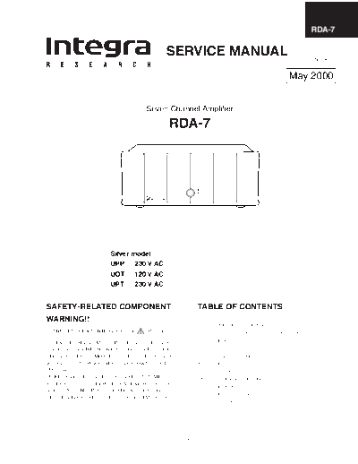
Image preview - the first page of the document

>> Download onkyo_integra_rda-7_amplifier_sm documenatation <<
Text preview - extract from the document
                                                                                                       RDA-7

                                            SERVICE MANUAL                                        Ref NO. 3651


                                                                                          May 2000


                                   Seven Channel Amplifier

                                            RDA-7


                      Silver model
                      UPP 230 V AC
                      UDT 120 V AC
                      UPT     230 V AC


SAFETY-RELATED COMPONENT                            TABLE OF CONTENTS
WARNING!!                                           1    Cover page
                                                    2    Specifications, Supplied accesories
COMPONENTS IDENTIFIED BY MARK      ON THE           3    Unpacking abd storing the packing materials
SCHEMATIC DIAGRAM AND IN THE PARTS LIST ARE         4    Front panel
CRITICAL FOR RISK OF FIRE AND ELECTRIC SHOCK.       5    Rear panel
REPLACE THESE COMPONENTS WITH ONKYO PARTS           7    Chassis-exploded view
WHOSE PART NUMBER APPEAR AS SHOWN IN THIS           8    Parts list
MANUAL.                                             16   Screws
MAKE LEAKAGE-CURRENT OR RESISTANCE MEA-             18   Adjustment procedures
SUREMENTS TO DETERMINE THAT EXPOSED PARTS
                                                    19   Pcboard
ARE ACCEPTABLY INSULATED FROM THE SUPPLY
                                                    20   Primary connections
CIRCUIT BEFORE RETURNING THE APPLIANCE TO
                                                    22   Circuit diagrams


                                                1
RDA-7

Specifications
AMPLIFIER SECTION
Number of channels:            7
Power:
   150 watts per channel min. RMS at 8 ohms, 2 channels
   driven from 20 Hz to 20 kHz with no more than 0.1 % total
   harmonic distortion.
   300 watts per channel min. RMS at 4 ohms, 2 channels
   driven at 1 kHz with no more than 0.1 % total harmonic
   distortion.
Frequency response @ -3 dB: 3.5 Hz - 250 kHz
Input Impedance:               47 kohm each phase
Input signal for max output power:
                               1.2 V
Input Sensitivity (Unbalanced):
                               100 mVrms
Input Sensitivity (Balanced): 200 mV
THD:                           0.03 %(20 Hz to 20 kHz)
Damping Factor:                40 at 8 ohm
Power consumption
  USA, Canada and some Asian model:
                               15 A
  Other models:                10 A
Rated Speaker Impedance:     4 ohms

GENERAL
Power Supply:                AC 120 V, 60 Hz
                             AC 230 V, 50 Hz
                             AC 220 V, 50/60 Hz
Dimensions (W
◦ Jabse Service Manual Search 2024 ◦ Jabse Pravopis ◦ onTap.bg ◦ Other service manual resources online : Fixya ◦ eServiceinfo