Service Manuals, User Guides, Schematic Diagrams or docs for : ONKYO DVD DPC-6 dpc6update_472
<< Back | HomeMost service manuals and schematics are PDF files, so You will need Adobre Acrobat Reader to view : Acrobat Download Some of the files are DjVu format. Readers and resources available here : DjVu Resources
For the compressed files, most common are zip and rar. Please, extract files with Your favorite compression software ( WinZip, WinRAR ... ) before viewing. If a document has multiple parts, You should download all, before extracting.
Good luck. Repair on Your own risk. Make sure You know what You are doing.
Image preview - the first page of the document
>> Download dpc6update_472 documenatation <<
Text preview - extract from the document
Final release date:02/27/01
DPC-6, DPC-6.1 Ref: 112200-2
Service Tip and Troubleshooting:
Make sure static free work environment is observed at all times when working with Laser Pickup.
Symptoms: (1) Disk Starts, Spins and DISK ERROR comes up.
(2) Disk plays with intermittent picture breaking up.
(3) Disk fails to initialize, or locks up trying to read disk.
(4) Plays DVD but fails to play CD or plays CD but not DVD.
Solution: Replace pickup connector cable. "Initial Change Over". See page 3 and 4 on how to test.
Old Part number New part Number Reason For change
2042183512 2042184012 Serviceability
2042180512 Eliminated Simplicity
1H412554-2 Eliminated Simplicity
Before you start work the following process must be addressed in order to avoid damage to the pickup assembly.
Your finding may resemble the followings:
a. Powers, rotates, carousel, chucks, (clamps) and LD is not ON, and immediately un-chuck.
b. Powers, chucks, and LD is on spins for a few seconds and unclamps goes to next disk.
c. Powers, chucks, LD is on, spins and spins trying to read TOC. Endless loop.
d. DVD plays but CD plays but not DVD.
e. Picture breakup problem.
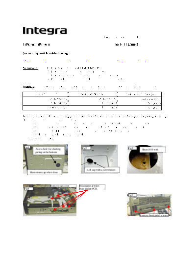
Fig1 Fig2 Fig3
Access hole for shorting Short J019 with
pickup at the bottom.
Lift cap with a screwdriver.
Must return cap when done.
Remove top cover Disconnect al wires
Fig4 from digital PCB.
Fig5
Remove front panel screws
Fig8
Fig6 Fig7 Latch
Carousel removed
Pull carousel forward with latch
Front and rear panel removed pushed down.
You may disconnect cable from
P111B
Fig10 Fig11
Remove two PCB mounting screws Bend the new cable
Fig9 and short pickup LD terminals. PN#2042184012 at the point of red
marking towards the marking.
The bend seen in Fig11 shall match this corner
(white mark). Return the clear vinyl as it was.
Use double side tape to attach cable.
Fig12 Re-assemble the unit back
and attach the cable as
illustrated next Fig14. It is
important to keep the pickup
shorted until last.
Connect cable PN#2042184012
directly to the pick-up. Please pay Fig13
attention to the BLUE BACK.
Make sure the cable at
Fig14 connector CN501 is curled to a
minimum to avoid cable break. Set the unit on its side and de-solder the
shorting from the pick up very carefully.
Core PN#230957 must be Fig15
installed at this point using
double side tape.
Bend cable as you see on this
picture. Please do not crush cable.
Solution: Replace pickup connector cable. "Second time around".
Fig16
If the shorting PCB seen in Fig 3 is not in place, you
will need to keep the DSP still connected to CN501
connector until pick-up shorting is done as seen on
figure 10. Keep DSP attached to the frame with an
electrical tape.
Test points and references:
A: make sure static free work environment is observed at all times when working with Laser Pickup.
With the unit totally turned OFF, confirm the impedance of the Focus Coil and the tracking coil at CN501. Between
pin 10 and 13, 8.2ohm for Focus coil and across pin 11 and 12, 8.3ohm for the Tracking Coil.
Check and verify procedure as given on page 43,44 of service manual. For disk to be recognized while carousel is
rotating but fail to spin and focus is a result of missing LD ON. This happens when one of the connectors at any of
the three points (Fig1 A, B and or Fig2 C) is lacking good contact to the ribbon.
***The laser pick needs no adjustment!!! ***
Do not forget to open pick-up shorting wire seen in Fig1 #1.
The troubleshooting guide given between pages of 43 and 50 is extremely helpful to determine the condition of the
PICKUP.
B: Disregarded Step 3 of page 45 and make correction as follows.
The reference should be:
lop = Voltage between
E522 and E523 3.3ohm
The voltage drop across R505 (3.3ohm) resistor is higher than 218~238mvDC in normal operating condition and the
LD is not on, connection (Fig1 A, B and or Fig2 C) may be loose or poor. This indicates the LD is not present as
load to the voltage rail R505.
The Individual optical output level may be monitored at the pickup connector point using an oscilloscope with no
more than 15pf input capacitance.
Example: Here are some common RF references taken using oscilloscope of 10meg/15pf with X10 probe.
WARNING: THESE TESTS (4,5,6,7,8,9) CAN NOT BE DONE UNLESS YOUR
OSCILOSCOPE PROBE HAS <10PF OF CAPACITANCE.
C: Connector CN501 starting from pin 4,5,6,7,8 and 9. may show the following reference signals while playing
DVD. For symptom (1), missing one of these signals could result Disk Reading message be displayed indefinitely
and lock the player in endless loop, or after numerous attempt Disk Error may be displayed.
87mv pp 87mv pp 160mv pp
110mv pp 110mv pp
160mv pp
For location refer to manual Page 50.
TP-515
D: To help reduce the break up of the video signal, remount CORE
#230957. The installation of this core should be as illustrated on Fig14.
** Since the root cause for the failure of DV-C600 and DV-C601 is
mainly noisy pick-up signal do to poor connector terminals, it is very
important all of the necessary steps mentioned are exhausted before
attempting to replace the PICKUP.
For additional info send technical question only to
[email protected]
◦ Jabse Service Manual Search 2024 ◦ Jabse Pravopis ◦ onTap.bg ◦ Other service manual resources online : Fixya ◦ eServiceinfo