Service Manuals, User Guides, Schematic Diagrams or docs for : AIWA Audio XC-RW700 hfe_aiwa_xc-rw700_service
<< Back | HomeMost service manuals and schematics are PDF files, so You will need Adobre Acrobat Reader to view : Acrobat Download Some of the files are DjVu format. Readers and resources available here : DjVu Resources
For the compressed files, most common are zip and rar. Please, extract files with Your favorite compression software ( WinZip, WinRAR ... ) before viewing. If a document has multiple parts, You should download all, before extracting.
Good luck. Repair on Your own risk. Make sure You know what You are doing.
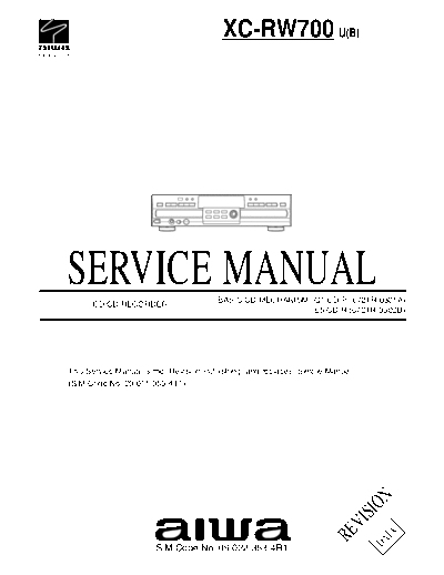
Image preview - the first page of the document

>> Download hfe_aiwa_xc-rw700_service documenatation <<
Text preview - extract from the document
                                         XC-RW700 U(B)


SERVICE MANUAL
      CD/CD RECORDER
                                        BASIC CD MECHANISM : Q1 CD-P (6721R-0301A)
                                                           : E5 CD-R (6721R-0302B)


This Service Manual is the "Revision Publishing" and replaces "Simple Manual"
(S/M Code No. 09-011-353-4T1).
                                                                                 N
                                                                                SIO
                                                                          VI
                                                                      RE

                                                                                   TA
                                                                                 DA


                       S/M Code No. 09-022-353-4R1
                                               TABLE OF CONTENTS

PROTECTION OF EYES FROM LASER BEAM DURING SERVICTNG -1/1 ........................................... 3
SPECIFICATIONS ...................................................................................................................................... 4
ACCESSORIES LIST -1/1 ......................................................................................................................... 5
DISASSEMBLY INSTRUCTIONS ......................................................................................................... 6 ~ 7
ELECTRICAL MAIN PARTS LIST ....................................................................................................... 8 ~ 10
TRANSISTOR ILLUSTRATION ................................................................................................................ 11
BLOCK DIAGRAM ............................................................................................................................ 12 ~ 15
WIRE HARNESS DIAGRAM -1/1 ............................................................................................................ 16
SCHEMATIC DIAGRAM
1/10 CD-P 1/2 SECTION ......................................................................................................................... 17
2/10 CD-P 2/2 SECTION ........................................................................................................................ 18
3/10 CD-R 1/4 SECTION ......................................................................................................................... 21
4/10 CD-R 2/4 SECTION ......................................................................................................................... 22
5/10 CD-R 3/4 SECTION ......................................................................................................................... 23
6/10 CD-R 4/4 SECTION ......................................................................................................................... 24
7/10 I/O SECTION ................................................................................................................................... 27
8/10 POWER SECTION ........................................................................................................................... 30
9/10 FRONT SECTION ............................................................................................................................ 32
10/10 POWERSW, PHONE SECTION .................................................................................................... 34
WIRING
1/11 CD-P C.B -SIDE A- ........................................................................................................................... 19
2/11 CD-P C.B -SIDE B- .......................................................................................................................... 20
3/11 CD-R C.B -SIDE A- .......................................................................................................................... 25
4/11 CD-R C.B -SIDE A- .......................................................................................................................... 26
5/11 I/O C.B -SIDE A- ............................................................................................................................... 28
6/11 I/O C.B -SIDE B- .............................................................................................................................. 29
7/11 POWER C.B ..................................................................................................................................... 31
8/11 FRONT C.B ...................................................................................................................................... 33
9/11 POWER SW C.B, PHONE C.B ........................................................................................................ 35
10/11 CD-P SECTION .............................................................................................................................. 36
11/11 CD-R SECTION .............................................................................................................................. 37
VOLTAGE CHART ............................................................................................................................ 38 ~ 41
WAVEFORMS ................................................................................................................................... 42 ~ 46
IC BLOCK DIAGRAM ........................................................................................................................ 47 ~ 53
IC DESCRIPTION ............................................................................................................................. 54 ~ 55
FL DISPLAY -1/1 ....................................................................................................................................... 56
MECHANICAL EXPLODED VIEW -1/1 ..................................................................................................... 57
MECHANICAL MAIN PARTS LIST -1/1 .................................................................................................... 58
COLOR NAME TABLE .............................................................................................................................. 59
CD-P MECHANISM EXPLODED VIEW -1/1 ............................................................................................ 60
CD-P MECHANISM MAIN PARTS LIST -1/1 ............................................................................................ 61
CD-R MECHANISM EXPLODED VIEW -1/1 ........................................................................................... 62
CD-R MECHANISM MAIN PARTS LIST -1/1 ............................................................................................ 63
TROUBLE SHOOTING ..................................................................................................................... 64 ~ 89


                                                                           -2-
PROTECTION OF EYES FROM LASER BEAM DURING SERVICING -1/1

This set employs laser. Therefore, be sure to follow carefully the                  CAUTION
instructions below when servicing.                                                  Use of controls or adjustments or performance of procedures other than
                                                                                    those specified herein may result in hazardous radiation exposure.
WARNING!
WHEN SERVICING, DO NOT APPROACH THE LASER EXIT WITH                                 ATTENTION
THE EYE TOO CLOSELY. IN CASE IT IS NECESSARY TO                                     L'utilisation de commandes, r
◦ Jabse Service Manual Search 2024 ◦ Jabse Pravopis ◦ onTap.bg ◦ Other service manual resources online : Fixya ◦ eServiceinfo