Service Manuals, User Guides, Schematic Diagrams or docs for : AOC Monitor E2251FWH aoc_e2251fwh_lcd_monitor
<< Back | HomeMost service manuals and schematics are PDF files, so You will need Adobre Acrobat Reader to view : Acrobat Download Some of the files are DjVu format. Readers and resources available here : DjVu Resources
For the compressed files, most common are zip and rar. Please, extract files with Your favorite compression software ( WinZip, WinRAR ... ) before viewing. If a document has multiple parts, You should download all, before extracting.
Good luck. Repair on Your own risk. Make sure You know what You are doing.
Image preview - the first page of the document
>> Download aoc_e2251fwh_lcd_monitor documenatation <<
Text preview - extract from the document
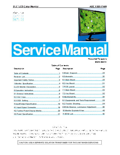
21.5" LCD Color Monitor AOC E2251FWH
Service
Service
Service
Horizontal Frequency
30kHz-83KHz
Table of Contents
Description Page Description Page
Table of Contents.........................................................1 5.Block Diagram............................................24
Revision List................................................................2 6.Schematic.......................................................25
Important Safety Notice...............................................3 6.1.Main Board....................................................25
1.Monitor Specification.................................................4 6.2.Key Board......................................................31
2.LCD Monitor Description.......................................5 7.PCB Layout.....................................................32
3.Operation Instruction...............................................6 7.1.Main Board....................................................32
3.1.General Instructions.................................................6 7.2.Key Board....................................................32
3.2.Hot Keys......................................................6 8.Maintainability..................................................33
3.3.OSD Setting.......................................................7 8.1.Equipments and Tools Requirement...............33
4.Input/Output Specification.......................................19 8.2.Trouble Shooting.........................................34
4.1.Input Signal Connector.........................................19 9.White-Balance, Luminance Adjustment.............38
4.2.Factory Preset Display Modes...............................20 10.Monitor Exploded View.................................40
4.3.Panel Specification.............................................21 11.BOM List..................................................42
SAFETY NOTICE
ANY PERSON ATTEMPTING TO SERVICE THIS CHASSIS MUST FAMILIARIZE HIMSELF WITH THE CHASSIS
AND BE AWARE OF THE NECESSARY SAFETY PRECAUTIONS TO BE USED WHEN SERVICING
ELECTRONIC EQUIPMENT CONTAINING HIGH VOLTAGES.
CAUTION: USE A SEPARATE ISOLATION TRANSFOMER FOR THIS UNIT WHEN SERVICING
Revision List
Version Release Date Revision History L&T Model Name
HIAJNZ2QB7A1CNF.LF
A00 JUL-20-2012 Add new CKD model
HIAJNZ2QB7A1CNF.PA
2
Important Safety Notice
Proper service and repair is important to the safe, reliable operation of all AOC Company Equipment. The service
procedures recommended by AOC and described in this service manual are effective methods of performing service
operations. Some of these service operations require the use of tools specially designed for the purpose. The
special tools should be used when and as recommended.
It is important to note that this manual contains various CAUTIONS and NOTICES which should be carefully read in
order to minimize the risk of personal injury to service personnel. The possibility exists that improper service
methods may damage the equipment. It is also important to understand that these CAUTIONS and NOTICES ARE
NOT EXHAUSTIVE. AOC could not possibly know, evaluate and advise the service trade of all conceivable ways in
which service might be done or of the possible hazardous consequences of each way. Consequently, AOC has not
undertaken any such broad evaluation. Accordingly, a servicer who uses a service procedure or tool which is not
recommended by AOC must first satisfy himself thoroughly that neither his safety nor the safe operation of the
equipment will be jeopardized by the service method selected.
Hereafter throughout this manual, AOC Company will be referred to as AOC.
WARNING
Use of substitute replacement parts, which do not have the same, specified safety characteristics may create shock,
fire, or other hazards.
Under no circumstances should the original design be modified or altered without written permission from AOC.
AOC assumes no liability, express or implied, arising out of any unauthorized modification of design.
Servicer assumes all liability.
FOR PRODUCTS CONTAINING LASER:
DANGER-Invisible laser radiation when open AVOID DIRECT EXPOSURE TO BEAM.
CAUTION-Use of controls or adjustments or performance of procedures other than those specified herein may
result in hazardous radiation exposure.
CAUTION -The use of optical instruments with this product will increase eye hazard.
TO ENSURE THE CONTINUED RELIABILITY OF THIS PRODUCT, USE ONLY ORIGINAL MANUFACTURER'S
REPLACEMENT PARTS, WHICH ARE LISTED WITH THEIR PART NUMBERS IN THE PARTS LIST SECTION OF
THIS SERVICE MANUAL.
Take care during handling the LCD module with backlight unit
-Must mount the module using mounting holes arranged in four corners.
-Do not press on the panel, edge of the frame strongly or electric shock as this will result in damage to the screen.
-Do not scratch or press on the panel with any sharp objects, such as pencil or pen as this may result in damage to
the panel.
-Protect the module from the ESD as it may damage the electronic circuit (C-MOS).
-Make certain that treatment person's body is grounded through wristband.
-Do not leave the module in high temperature and in areas of high humidity for a long time.
-Avoid contact with water as it may a short circuit within the module.
-If the surface of panel becomes dirty, please wipe it off with a soft material. (Cleaning with a dirty or rough cloth may
damage the panel.)
3
1. Monitor Specifications
4
2. LCD Monitor Description
The LCD MONITOR will contain a main board and a key board which house the flat panel control logic, brightness
control logic and DDC.
Monitor Block Diagram
Flat Panel and
LED Drive.
LED backlight
Key Board
Main Board
HDMI DVI D-SUB Audio
Adapter Signal Signal Signal out
AC-IN
100V~24
5
3. Operating Instructions
3.1 General Instructions
Press the power button to turn the monitor on or off. The other control knobs are located at front panel of the monitor.
By changing these settings, the picture can be adjusted to your personal preferences.
3.2 Hotkeys
Power
Press the Power button to turn on/off the monitor.
Menu/Enter
Press to display the OSD or confirm the selection
Eco (DCR)/-
Press the Eco key continuously to select the Eco mode of brightness and DCR on when there is no OSD. (Eco
mode hot key may not be available in all models).
4:3 or wide image ratio /Volume >
When there is no OSD and VGA input only, press hotkey continuously to change 4:3 or wide image ratio.
(If the product screen size is 4:3 or input signal resolution is wide format, the hot key is disable to adjust
and also only available for VGA input )
when HDMI input, press hotkey continuously to activate Volume, and press the Up or Down to change
the setting, press Menu button for confirmation and exit OSD. this only available for HDMI input
Source/Auto / Exit
When the OSD is closed, press Auto/Source/Exit button continuously about 2 second to do auto configure (only for
the models with dual or more inputs).
When the OSD is closed, press Auto/Source/Exit button will be Source hot key function (Only for the models with
dual or more inputs).
6
3.3 OSD Setting
Basic and simple instruction on the control keys.
1) Press the MENU-button to activate the OSD window.
2) Press < or > to navigate through the functions. Once the desired function is highlighted, press the
MENU-button to activate sub-menu . Once the desired function is highlighted, press MENU-button to activate
it.
3) Press or to change the settings of the selected function. Press AUTO to exit. If you want to
adjust any other function, repeat steps 2-3.
4) OSD Lock Function: To lock the OSD, press and hold the MENU button while the monitor is off and then
press power button to turn the monitor on. To un-lock the OSD - press and hold the MENU button while
the monitor is off and then press power button to turn the monitor on.
Notes:
1) If the product has only one signal input, the item of "Input Select" is disable to adjust.
2) If the product screen size is 4:3 or input signal resolution is wide format, the item of "Image Ratio" is disable to
adjust.
3) One of DCR, Color Boost, and Picture Boost functions is active, the other two function is turned off accordingly.
7
Luminance
1
Press (Menu) to display menu
2
Press or to select (Luminance), and press to enter
3
Press or to select submenu, and press to enter.
8
4
Press or to adjust
5
Press to exit.
9
Image Setup
1
Press (Menu) to display menu
2
Press or to select (Image Setup) , and press to enter.
3
Press or to select submenu, and press to enter.
4
Press or to adjust.
10
5
Press to exit.
Clock 0-100 Adjust picture Clock to reduce Vertical-Line noise.
Phase 0-100 Adjust Picture Phase to reduce Horizontal-Line noise
Sharpness 0-100 Adjust picture sharpness
H.Position 0-100 Adjust the horizontal position of the picture.
V.Position 0-100 Adjust the vertical position of the picture.
Color Setup
1
Press (Menu) to display menu.
2
Press or to select (Color Setup), and press to enter.
11
3
Press or to select submenu, and press to enter.
4
Press or to adjust.
5
Press to exit.
12
Warm Recall Warm Color Temperature from EEPROM.
Normal Recall Normal Color Temperature from EEPROM.
Cool Recall Cool Color Temperature from EEPROM.
Color setup. sRGB Recall SRGB Color Temperature from EEPROM.
Red Red Gain from Digital-register
User Green Green Gain Digital-register.
Blue Blue Gain from Digital-register
Full
on or off Disable or Enable Full Enhance Mode
Enhance
Nature Skin on or off Disable or Enable Nature Skin Mode
DCB Mode
Green Field on or off Disable or Enable Green Field Mode
Sky-blue on or off Disable or Enable Sky-blue Mode
AutoDetect on or off Disable or Enable AutoDetect Mode
DCB Demo on or off Disable or Enable Demo
Picture Boost
1
Press (Menu) to display menu.
2
Press or to select (Picture Boost), and press to enter.
13
3
Press or to select submenu, and press to enter.
4
Press or to adjust.
5
Press to exit.
Frame Size 14-100 Adjust Frame Size
Brightness 0-100 Adjust Frame Brightness
Contras 0-100 Adjust Frame Contrast
H. position 0-100 Adjust Frame horizontal Position
V.position 0-100 Adjust Frame vertical Position
Bright Frame on or off Disable or Enable Bright Frame
14
OSD Setup
1
Press (Menu) to display menu.
2
Press or to select (OSD Setup), and press to enter.
3
Press or to select submenu, and press to enter.
15
4
Press or to adjust.
5
Press to exit.
H.Position 0-100 Adjust the horizontal position of OSD
V.Position 0-100 Adjust the vertical position of OSD
Timeout 5-120 Adjust the OSD Timeout
Transparence 0-100 Adjust the transparence of OSD
Language Select the OSD language
Extra
1
Press (Menu) to display menu.
16
2
Press or to select (Extra), and press to enter.
3
Press or to select submenu, and press to enter.
4
Press or to adjust.
5
Press to exit.
17
Exit
1
Press (Menu) to display menu.
2
Press or to select (Exit), and press to exit.
Exit Exit the main OSD
18
4. Input/Output Specification
4.1 D-SUB CONNECTORS and DVI CONNECTORS
Pin Assignments
Pin Number 15-Pin Side of the Signal Cable Pin Number 15-Pin Side of the Signal Cable
1 Video-Red 9 +5V
2 Video-Green 10 Ground
3 Video-Blue 11 N.C.
4 N.C. 12 DDC- Serial data
5 Detect Cable 13 H- sync
6 GND-R 14 V- sync
7 GND-G 15 DDC- Serial clock
8 GND-B
Pin Number 24-Pin Color Display Signal Cable Pin Number 24-Pin Color Display Signal Cable
1 TMDS data 2 13 TMDS data 3
2 TMDS data 2 14 5V Power
3 TMDS data 2/4 Shield 15 Ground +5V
4 TMDS data 4 16 Hot Plug Detect
5 TMDS data 4 17 TMDS data 0
6 DDC Clock 18 TMDS data 0
7 DDC data 19 TMDS data 0/5 Shield
8 N.C. 20 TMDS data 5
9 TMDS data 1 21 TMDS data 5
10 TMDS data 1 22 TMDS Clock Shield
11 TMDS data 1/3 Shield 23 TMDS Clock +
12 TMDS data 3 24 TMDS Clock
19
4.2 Factory Preset Display Modes
20
4.3 Panel Specification
4.3.1 General Features
BM215WF4-TJC1 is a Color Active Matrix Liquid Crystal Display with an integral Light Emitting Diode (LED)
backlight system. The matrix employs a-Si Thin Film Transistor as the active element. It is a transmissive type
display operating in the normally white mode. It has a 21.5 inch diagonally measured active display area with Full
HD resolution (1080 vertical by 1920 horizontal pixel array) Each pixel is divided into Red, Green and Blue
sub-pixels or dots which are arranged in vertical stripes. Gray scale or the brightness of the sub-pixel color is
determined with
a 8-bit gray scale signal for each dot, thus, presenting a palette of more than 16,7M colors with
Advanced-FRC(Frame Rate Control). It has been designed to apply the interface method that enables low power,
high speed, low EMI. FPD Link or compatible must be used as a LVDS(Low Voltage Differential Signaling) chip. It is
intended to support applications where thin thickness, wide viewing angle, low power are critical factors and graphic
displays are important. In combination with the vertical arrangement of the sub-pixels, the BM215WF4-TJC1
characteristics provide an excellent flat panel display for office automation products such as monitors.
4.3.2 Display Characteristics
21
4.3.3 Electrical Characteristics
Values
Parameter Symbol Unit Notes
Min Typ Max
MODULE :
Power Supply Input Voltage VLCD 4.5 5.0 5.5 Vdc
Permissive Power Input Ripple VLCD - - 0.3 V 3
ILCD-MOSAIC(60Hz) - 1000 1300 mA 1,5
Power Supply Input Current ILCD-BLACK(60Hz) - 1300 1690 mA 2,5
ILCD-BLACK(75Hz) - 2000 mA 5
Power Consumption PLCD - 5.00 6.5 Watt 1
Inrush current IRUSH - - 3.0 A 1, 4
LED bar Electrical characteristics
Values
Parameter Symbol Condition Unit Notes
Min. Typ. Max.
LED : 1,7
LED String Current Is - 110 120 mA 2,7
LED String Voltage Vs 48.0 51.2 54.4 V 3,7
Power Consumption PBar - 11.3 12.0 Watt 4,6,7
LED Life Time LED_LT 30,000 - - Hrs 5,7
22
4.3.4 Optical Characteristics
Ta=25 ◦ Jabse Service Manual Search 2024 ◦ Jabse Pravopis ◦ onTap.bg ◦ Other service manual resources online : Fixya ◦ eServiceinfo