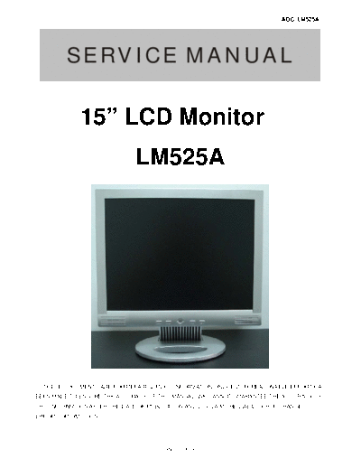
Service Manuals, User Guides, Schematic Diagrams or docs for : AOC Monitor LM525A
<< Back | HomeMost service manuals and schematics are PDF files, so You will need Adobre Acrobat Reader to view : Acrobat Download Some of the files are DjVu format. Readers and resources available here : DjVu Resources
For the compressed files, most common are zip and rar. Please, extract files with Your favorite compression software ( WinZip, WinRAR ... ) before viewing. If a document has multiple parts, You should download all, before extracting.
Good luck. Repair on Your own risk. Make sure You know what You are doing.
Image preview - the first page of the document

>> Download LM525A documenatation <<
Text preview - extract from the document
                                                                             AOC LM525A


         SERVICE MANUAL

              15" LCD Monitor
                               LM525A


  THESE DOCUMENTS ARE FOR REPAIR SERVICE INFORMATION ONLY. EVERY REASONABLE EFFORT HAS
BEEN MADE TO ENSURE THE ACCURACY OF THIS MANUAL; WE CANNOT GUARANTEE THE ACCURACY OF
THIS INFORMATION AFTER THE DATE OF PUBLICATION AND DISCLAIMS RE LIABILITY FOR CHANGES,
ERRORS OR OMISSIONS.


                                         Page 1 of 49
                                                                                                                        AOC LM525A
                                                          Table of Content
Revision List.........................................................................................................................   3
1. Monitor Specifications........................................................................................................        4
2. LCD Monitor Description.....................................................................................................          5
3. Operating Instructions........................................................................................................        6
  3.1 General Instructions.........................................................................................................      6
  3.2 Front Panel Control..........................................................................................................      6
  3.3 Adjusting the Picture........................................................................................................      7
4. Input/Output Specification...................................................................................................         9
  4.1 Input Signal Connector.....................................................................................................        9
  4.2 Factory Preset Display Modes............................................................................................           10
  4.3 Power Supply Requirements.............................................................................................             10
  4.4 Panel Specification..........................................................................................................      11
     4.4.1 Panel Feature...........................................................................................................      11
     4.4.2 Display Characteristics...............................................................................................        11
     4.4.3 Optical Characteristics................................................................................................       12
     4.4.4 Parameter Guide Line For CCFL Inverter........................................................................                12
5. Block Diagram...................................................................................................................      13
  5.1 Monitor Exploded View.....................................................................................................         13
  5.2 Software Flow Chart.........................................................................................................       14
  5.3 Electrical Block Diagram...................................................................................................        16
     5.3.1 Main Board..............................................................................................................      16
     5.3.2 Inverter/Power Board..................................................................................................        17
6. Schematic.........................................................................................................................    18
  6.1 Main Board....................................................................................................................     18
  6.2 Power Board..................................................................................................................      24
  6.3 Audio Board...................................................................................................................     26
7. PCB Layout......................................................................................................................      27
  7.1 Main Board....................................................................................................................     27
  7.2 Power Board..................................................................................................................      28
  7.3 Audio Board...................................................................................................................     28
  7.4 Keypad Board................................................................................................................       28
8. Maintainability...................................................................................................................    29
  8.1 Equipments and Tools Requirement....................................................................................               29
  8.2 Trouble Shooting.............................................................................................................      30
     8.2.1 Main Board...............................................................................................................     30
     8.2.2 Power /Inverter/Board.................................................................................................        33
     8.2.3 Keypad Board...........................................................................................................       35
9. White-Balance, Luminance adjustment.................................................................................                  36
10. EDID Content...................................................................................................................      37
11. BOM LIST.........................................................................................................................    38


                                                             Page 2 of 49
                                                            AOC LM525A

                       Revision List
Revision     Date                  Change Description
  A00      Oct-29-05                    Original Revision


                         Page 3 of 49
                                                                                          AOC LM525A
1. MONITOR SPECIFICATIONS
                          Driving system                 TFT LCD

                          Size                           38.1cm(15.0")

                          Type                           HSD150MX15HSD

                          Pixel pitch                    0.297mm(H) x 0.297mm(V)

                          Viewing angle                  160(H) 115(V) (CR>5)
        LCD Panel
                          Luminance                      250cd/ m2

                          Contrast Ratio                 500:1

                          Response time                  25ms (typ)

                          Display colors                 16 million (6 bit + FRC)

                          R G B Analog                   0.7Vp-p

                          H/V separate                   TTL level

       Input signals      H/V composite                  TTL level

                          Horizontal frequency           30kHz
◦ Jabse Service Manual Search 2024 ◦ Jabse Pravopis ◦ onTap.bg ◦ Other service manual resources online : Fixya ◦ eServiceinfo