Service Manuals, User Guides, Schematic Diagrams or docs for : AOC Monitor LM520i
<< Back | HomeMost service manuals and schematics are PDF files, so You will need Adobre Acrobat Reader to view : Acrobat Download Some of the files are DjVu format. Readers and resources available here : DjVu Resources
For the compressed files, most common are zip and rar. Please, extract files with Your favorite compression software ( WinZip, WinRAR ... ) before viewing. If a document has multiple parts, You should download all, before extracting.
Good luck. Repair on Your own risk. Make sure You know what You are doing.
Image preview - the first page of the document
>> Download LM520i documenatation <<
Text preview - extract from the document
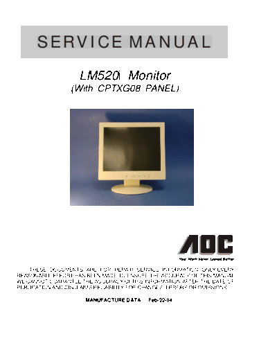
      SERVICE MANUAL
                    LM520i Monitor
                 (With CPTXG08 PANEL)


    THESE DOCUMENTS ARE FOR REPAIR SERVICE INFORMATION ONLY.EVERY
REASONABLE EFFORT HAS BEEN MADE TO ENSURE THE ACCURACY OF THIS MANUAL;
WE CANNOT GUARANTEE THE ACCURACY OFTHIS INFORMATION AFTER THE DATE OF
PUBLICATION AND DISCLAIMS RELIABILITY FOR CHANGES, ERRORS OR OMISSIONS.

                      MANUFACTURE DATA Feb-22-04
                                                      TABLE OF CONTENTS
PAGE
  1. SPECIFICATIONS ....................................................................................................         3
     1-1  GENERAL SPECIFICATIONS ....................................................................                            3
     1-2 LCD MONITOR DESCRIPTION ..................................................................                              4
     1-3  INTERFACE CONNECTOR ........................................................................                           4

   2.    PRECAUTION AND NOTICES ................................................................................                  5
         2-1 ASSEMBLY PRECAUTION .........................................................................                        5
         2-2 OPERATIONG PRECAUTION .....................................................................                          5
         2-3 STORAGE PRECAUTION ...........................................................................                       5
         2-4 HIGH VOLTAGE WARNING .......................................................................                         5

   3.    OPERATING INSTRUCTIONS ................................................................................                  6

   4.    ADJUSTMENT ..........................................................................................................    7
         4-1 ADJUSTMENT CONDITIONS AND PRECAUTIONS ...............................                                                7
         4-2 ADJUSTMENTS METHOD .& DESCRIPTION...........................................                                         7
         4-3 FRONT PANEL CONTROL KNOBS ............................................................                               8

   5.    CIRCUIT & SOFTWARE DESCRIPTION ................                                                                          9
         5-1 THE DIFFERENT BETWEEN EACH PANEL ..................................                                                  9
         5-2 SPECIAL FUNCTION WITH PRESS KEY ......................................                                              10
         5-3  SIMPLE INTRODUCTION ABOUT LM500 CHIPSET ........................                                                   11
         5-4  SOFTWARE FLOW-CHART                                                                                                13

   6.    TROUBLE SHOOTING.............................................................................................           15
           A).MAIN BOARD TROUBLE SHOOTING CHART .. ....................................                                          15
         B). INVERTER - MODULE TROUBLE SHOOTING CHART ...........................                                                19

   7.    MECHANICAL OF CABINET FRONT DIS-ASSEMBLY......................................                                          21

   8.    PARTS LISTING .....................................................................................................     22

   9.    SCHEMATIC................................................................................................               34

   10. PCB LAYOUT ...................................................................................................            37


                                                                        2
                                        1. SPECIFICATIONS FOR LCD MONITOR

1-1        General specifications
      1.    LCD-PANEL :
            Active display area         15 inches or 15.1 inches diagonal
            Pixel pitch                 0.297 mm x 0.297 mm
            Pixel format                1024 x 768 RGB vertical stripe arrangement

      2.    Display Color :
            6-bit, 262144 colors or 8-bit, 16.7 million colors

      3.    External Controls :
            a).Power On/Off, Auto key, Rotary-knob ( for shuttle)
            b).Power On/Off, Auto key, Left key, Right key ( for 4-key )
            OSD menu Controls
             Contrast, Brightness, Focus, Clock,H-position, V-position, Language, Recall-C2(warm color), Recall-C1 (Cool
            color), Reset, Exit-OSD, Red, Green, Blue

      4.    Input Video Signal :
            Analog-signal 0.7Vpp
            Video signal termination impedance 75 OHM

      5.    Scanning Frequencies :
            Horizontal:    29 KHz - 63 KHz
            Vertical:      55 Hz
◦ Jabse Service Manual Search 2024 ◦ Jabse Pravopis ◦ onTap.bg ◦ Other service manual resources online : Fixya ◦ eServiceinfo