Service Manuals, User Guides, Schematic Diagrams or docs for : Agilent HP 8559 Service A
<< Back | HomeMost service manuals and schematics are PDF files, so You will need Adobre Acrobat Reader to view : Acrobat Download Some of the files are DjVu format. Readers and resources available here : DjVu Resources
For the compressed files, most common are zip and rar. Please, extract files with Your favorite compression software ( WinZip, WinRAR ... ) before viewing. If a document has multiple parts, You should download all, before extracting.
Good luck. Repair on Your own risk. Make sure You know what You are doing.
Image preview - the first page of the document
>> Download HP 8559 Service A documenatation <<
Text preview - extract from the document
OPERATION AND SERVICE ANUAL
SPECTRUM ANALYZER
Hewlett-Packard Company certifies that this product met its published specifications at the time o f
shipment from the factory. Hewlett-Packard further certij?es that its calibration measurements are
traceable to the United States National Bureau of Standards, to the extent allowed b y the Bureau's
calibration facility. and t o the calibration facilities of other International Standards Organization
members.
WARRANTY
This Hewlett-Packard instrument product is warranted against defects in material and workmanship
for a period of one year from date of shipment. During the warranty period, Hewlett-Packard Com-
pany will, at its option, either repair or replace products which prove to be defective.
For warranty service or repair, this product must be returned to a service facility designated by HP.
Buyer shall prepay shipping charges to HP and HP shall pay shipping charges t o return the product t o
Buyer. However, Buyer shall pay all shipping charges, duties, and taxes for products returned to HP
from another country.
HP warrants that its software and firmware designated by HP for use with an instrument will execute
its programming instructions when properly installed on that instrument. HP does not warrant that the
operation of the instrument, or software, or firmware will be uninterrupted or error free.
LIMITATION 0F WARRANTY
The foregoing warranty shall not apply to defects resulting from improper or inadequate maintenance
by Buyer, Buyer-supplied software or interfacing, unauthorized modification or misuse, operation
outside of the environmental specifications for the product, or improper site preparation or main-
tenance.
NO OTHER WARRANTY IS EXPRESSED OR IMPLIED. HP SPECIFICALLY DISCLAIMS THE JM-
PLIED WARRANTIES OF MERCHANTABILITY AND FITNESS FOR A PARTICULAR PURPOSE.
EXCLUSIVE REMEDIES
THE REMEDIES PROVIDED HEREIN ARE BUYER'S SOLE AND EXCLUSIVE REMEDIES. HP
SHALL NOT BE LIABLE FOR ANY DIRECT, INDIRECT, SPECIAL, INCIDENTAL, OR CONSE-
QUENTIAL DAMAGES, WHETHER BASED ON CONTRACT, TORT, OR ANY OTHER LEGAL
THEORY.
ASSISTANCE
Product maintenance agreements and other customer assistance agreements are available for Hewlett-
Packard products.
For any assistance, contact your nearest Hewlett-Packard Sales and Sewice Office. Addresses are
provided at the back of this manual.
HEWLETT
PACKARD
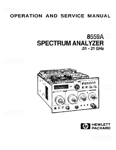
OPERATION AND SERVICE MANUAL
8559A
SPECTRUM ANALYZER
0.1 - 21 GHz
SERIAL NUMBERS
This manual applies directly to instruments with
serial numbers prefixed 2347A.
With modifications described in Section VII, this
manual also applies to instruments with serial num-
ber prefixes 1909A through 2320A.
For additional information about serial numbers, see
INSTRUMENTS COVERED BY MANUAL in
Section I.
COPYRIGHT O HEWLETT-PACKARD COMPANY, 1979,1983
1424 FOUNTAINGROVE PARKWAY, SANTA ROSA, CALIFORNIA, 95401, USA
MANUAL PART NUMBER 08559-90012
Microfiche Part Number 08559-90013 Printed: January 1984
CONTENTS
Section Page Section Page
I GENERAL INFORMATION . . . . . . . . . . . . . . 1-1 3-29. Display Adjustments-HP 853A
1-1. Introduction . . . . . . . . . . . . . . . . . . . . 1-1 Spectrum Analyzer Display . . . . . . . . 3-3
1-3. Description . . . . . . . . . . . . . . . . . . . . 1-1 3-30. Display Adjustments-HP 180-Series
1-6. Manual Organization . . . . . . . . . . . . . . 1-1 Display Mainframe . . . . . . . . . . . . . . 3-3
1-9. Specifications . . . . . . . . . . . . . . . . . . . 1-1 3-31. Frequency and Amplitude Adjustments. 3-4
1-11. Safety Considerations . . . . . . . . . . . . . . 1-2
1-13. Instruments Covered by Manual . . . . . . . 1-2 IV PERFORMANCE TESTS . . . . . . . . . . . . . . . .4 - 1
1-14. Serial Numbers . . . . . . . . . . . . . . . . . 1-2 4-1. Introduction . . . . . . . . . . . . . . . . . . . . 4-1
1-16. Manual Updating Supplement . . . . . . . 1-2 4-3. Instruments Tested . . . . . . . . . . . . . . . 4-1
1-19. Manual Backdating Changes . . . . . . . . . 1-2 4-5. Equipment Required . . . . . . . . . . . . . . 4-1
1-22. Accessories Supplied . . . . . . . . . . . . . . 1-2 4-7. Test Record . . . . . . . . . . . . . . . . . . . . 4-1
1-26. Equipment Required 4-9. Calibration Cycle. . . . . . . . . . . . . . . . . 4-1
Not Supplied . . . . . . . . . . . . . . . . . 1-10 4-1 1. Frequency Span Accuracy . . . . . . . . . . . 4-2
1-27. Display Mainframe . . . . . . . . . . . . . . 4-12. Tuning Accuracy . . . . . . . . . . . . . . . . . 4 - 7
1-30. Extender Cable Assembly . . . . . . . . . 1-10 4- 1 3. Residual FM . . . . . . . . . . . . . . . . . . . 4-10
1-32. Equipment and Accessories Available . . .1-10 4-14. Noise Sidebands . . . . . . . . . . . . . . . . 4-12
1-33. Input Limiter . . . . . . . . . . . . . . . . . 1-10 4-15. Resolution Bandwidth Accuraacy . . . . . 4-14
1-37. Modification Kit (Option 807 4-16. Resolution Bandwidth Selectivity . . . . . 4-20
Connections) . . . . . . . . . . . . . . . . 1-10 4-17. Average Noise Level . . . . . . . . . . . . . . 4-25
1-39. Oscilloscope Camera . . . . . . . . . . . . 1-10 4-18. Residual Responses . . . . . . . . . . . . . . 4-28
1-41. Service Accessories . . . . . . . . . . . . . . 1-10 4-19. Frequency Response . . . . . . . . . . . . . 4-30
1-43. Recommended Test Equipment . . . . . . 1-10 4-20. GainCompression . . . . . . . . . . . . . . . 4-39
4-21. Bandwidth Switching (Amplitude
II INSTALLATION AND OPERATION Variation) . . . . . . . . . . . . . . . . . . . 4-42
VERIFICATION . . . . . . . . . . . . . . . . . . . . . 2-1 4-22. Input Attenuator Accuracy . . . . . . . . . 4 - 44
2-1. Introduction . . . . . . . . . . . . . . . . . . . . 2 - 1 4-23. Reference Level Accuracy . . . . . . . . . . 4-47
2-3. Initial Inspection . . . . . . . . . . . . . . . . . 2-1 4-24. Sweep Time Accuracy . . . . . . . . . . . . 4-52
2-5. Preparation for Use . . . . . . . . . . . . . . . 2-1 4-25. Calibrator Output Accuracy . . . . . . . . 4 - 57
2-6. Installation . . . . . . . . . . . . . . . . . . . . 2 - 1 4-26. Display Fidelity . . . . . . . . . . . . . . . . 4-58
2-9. Side Stop Kits . . . . . . . . . . . . . . . . . . 2 - 1
2-14. Graticule Overlays . . . . . . . . . . . . . . . 2-3 ADJUSTMENTS . . . . . . . . . . . . . . . . . . . . . . 5 - 1
2-17. Operating Environment . . . . . . . . . . . 2 - 3 5-1. Introduction . . . . . . . . . . . . . . . . . . . .5-1
2-19. Modifications . . . . . . . . . . . . . . . . . . 2-3 5-4. Equipment Required . . . . . . . . . . . . . .5 - 1
2-21. Storage and Shipment . . . . . . . . . . . . . 2-4 5-6. Adjustment Tools . . . . . . . . . . . . . . . 5 - 1
2-22. Environment . . . . . . . . . . . . . . . . . . 2-4 5-9. Extender Cable Installation . . . . . . . . . 5-1
2-24. Packaging . . . . . . . . . . . . . . . . . . . . . 2-4 5 - 13. Related Adjustments . . . . . . . . . . . . . . 5-2
2-27. Operation Verification . . . . . . . . . . . . . 2-4 5-14. Factory Selected Components . . . . . . . . 5 - 2
5- 17. Power Supply Checks and Adjustments . 5- 11
III OPERATION . . . . . . . . . . . . . . . . . . . . . . . . 3-1 5-18. Calibrated Sweep Time Adjustment . . . 5 - 14
3-1 Introduction. . . . . . . . . . . . . . . . . . . . 3-1 5-19. Log Amplifier Log and
3-4 Description . . . . . . . . . . . . . . . . . . . . 3-1 Linear Adjustments . . . . . . . . . . . . . 5-17
3-5 HP 8559A Spectrum Analyzer . . . . . . . 3-1 5-20. 1-dB Offset Adjustment . . . . . . . . . . . 5-24
3-7 HP 853A Spectrum Analyzer Display . . 3-1 5-21. Bandwidth Filter Adjustments . . . . . . . 5-26
3-9 HP.IB . . . . . . . . . . . . . . . . . . . . . . . 3 - 1 5-22. 3-dB Bandwidth Adjustments . . . . . . . 5-33
3-11 Controls, Indicators, and Connectors . . . . 3-1 5-23. RF Gain Adjustment . . . . . . . . . . . . . 5-38
3-12 Control Grouping . . . . . . . . . . . . . . . 3-1 5-24. Step Gain Adjustments . . . . . . . . . . . . 5-41
3-20 Operating Precautions . . . . . . . . . . . . . 3-2 5-25. First Converter Adjsutments . . . . . . . . 5-44
3-21 Signal Input . . . . . . . . . . . . . . . . . . . 3-2 5-26. Second Converter Adjustments . . . . . . 5-49
3-23 Line Power On . . . . . . . . . . . . . . . . . 3-2 5-27. Third Converter Adjustments . . . . . . . . 5-54
3-27 Front-Panel Adjustment Procedure . . . . . 3-2 5-28. Frequency Response Adjustments . . . . 5-57
ii
CONTENTS
Section Page Section Page
5-29. Cal Output and Ref Level Cal VIII SERVICE . . . . . . . . . . . . . . . . . . . . . . . . . . 8-1
Adjustments . . . . . . . . . . . . . . . . . . 5-66 8-1. Introduction . . . . . . . . . . . . . . . . . . . . 8- 1
5-30. Frequency Display Adjustments . . . . . . 5-69 8-3. Schematic Symbols, Terminology.
and Voltage Levels. . . . . . . . . . . . . . . 8- 1
VI REPLACEABLE PARTS . . . . . . . . . . . . . . . . 6- 1 8-5. Test Equipment . . . . . . . . . . . . . . . . . 8- 1
6-1 Introduction . . . . . . . . . . . . . . . . . . . . 6-1 8-7. Major Assembly Locations . . . . . . . . . . 8- 1
6-3. Replaceable Parts List . . . . . . . . . . . . . 6-1 8-9. Troubleshooting . . . . . . . . . . . . . . . . . 8- 1
6-6. Ordering Information . . . . . . . . . . . . . . 6-1 8-10. General Information . . . . . . . . . . . . . . 8-1
8-12. Printed Circuit Board Edge Connector
VII MANUAL BACKDATING CHANGES . . . . . . . . 7- 1 Contact Cleaning . . . . . . . . . . . . . . . . 8-2
7-1. Introduction . . . . . . . . . . . . . . . . . . . . 7-1 The HP 8559A Spectrum Analyzer
7-4. How to Use This Backdating Theory of Operation . . . . . . . . . . . . . . . . . . 8-9
Information . . . . . . . . . . . . . . . . . . . 7- 1 Troubleshooting Hints . . . . . . . . . . . . . . . . . 8-12
MODEL 8559A GENERAL INFORMATION
SAFETY SYMBOLS
The following safety symbols are used throughout this manual and in the instrument. Familiarize
yourself with each of the symbols and its meaning before operating this instrument.
Instruction manual symbol. The instrument will be marked with this symbol
when it is necessary for the user to refer to the instruction manual in order to
protect the instrument against damage. Location of pertinent information
within the manual is indicated by use of this symbol in the table of contents.
// Indicates dangerous voltages are present. Be extremely careful.
The CAUTION sign denotes a hazard. It calls attention to a procedure which, if
not correctly performed or adhered to, could result in damage to or destruction
of the instrument. Do not proceed beyond a CAUTION sign until the indicated
conditions are fully understood and met.
The WARNING sign denotes a hazard. It calls attention to a procedure which,
if not correctly performed or adhered to, could result in injury or loss of life.
Do not proceed beyond a WARNING sign until the indicated conditions are
fully understood and met.
GENERAL SAFETY CONSIDERATIONS
BEFORE THlS INSTRUMENT IS SWITCHED ON, make sure it has been
properly grounded through the protective conductor of the ac power cable
to a socket outlet provided with protective earth contact. Any interruption of
the protective (grounding) conductor, inside or outside the instrument, or
disconnection of the protective earth terminal can result in personal injury.
There are voltages at many points in the instrument which can, if contacted,
cause personal injury. Be extremely careful. Any adjustments or service pro-
cedures that require operation of the instrument with protective covers
removed should be performed only by trained service personnel.
BEFORE THlS INSTRUMENT IS SWITCHED ON, make sure its primary
power circuitry has been adapted to the voltage of the ac power source.
Failure to set the ac power input to the correct voltage could cause damage
to the instrument when the ac power cable is plugged in.
GENERAL INFORMATION MODEL 8559A
SPECTRUM ANALYZER
ADAPTER SIDE STOP K I T OVERLAY K I T
1250-0780 08558-60131 5060-0319
FIGURE 1-1. HP MODEL8559ASPECTRUM ANALYZER AND ACCESSORIES SUPPLIED
1-0
MODEL 8559A GENERAL INFORMATION
SECTION I
GENERAL INFORMATION
1-1. INTRODUCTION SECTION IV, PERFORMANCE TESTS; con-
tains the necessary tests to verify that the elec-
1-2. This Operation and Service manual contains trical operation of the instrument is in accord-
information required to install, operate, test, adjust, ance with published specifications.
and service the Hewlett-Packard 8559A Spectrum
Analyzer. Figure 1-1 shows the instrument and acces- SECTION V, ADJUSTMENTS; contains the
sories supplied. This section covers instrument identi- necessary adjustment procedures to properly
fication, description, options, accessories, specifica- adjust the instrument after repair.
tions, and other basic information.
SECTION VI, REPLACEABLE PARTS; con-
tains the information necessary to order parts
1-3. DESCRIPTION and/or assemblies for the instrument.
SECTION VII, MANUAL BACKDATING
1-4. The H P 8559A displays the amplitude and fre- CHANGES; contains backdating information
quency of each component of an input signal on a to make this manual compatible with earlier
CRT. This display gives quantitative information equipment configurations.
often not available from a conventional oscilloscope.
The H P 8559A is capable of measuring signals from SECTION VIII, SERVICE; contains schematic
- 112 dBm to + 30 dBm over a frequency range of diagrams, block diagrams, component location
10 MHz to 21 GHz. illustrations, circuit descriptions, and trouble-
shooting information to aid in repair of the
1-5. The complete measuring system includes the instrument.
H P 8559A Spectrum Analyzer plugged into a com-
patible Hewlett-Packard display mainframe. 1-8. On the title page of this manual, below the
manual part number, is a microfiche part number.
This number may be used to order 4- by 6-inch
1-6. MANUAL ORGANIZATION microfilm transparencies of the manual. Each micro-
fiche contains up to 60 photo-duplicates of the man-
ual pages. The microfiche package also includes the
1-7. This manual is divided into eight sections as latest Manual Updating supplement.
follows:
1-9. SPECIFICATIONS
SECTION I, GENERAL INFORMATION;
contains the instrument description and specifi- 1-10. Instrument specifications are listed in Table
cations, explains accessories and options, and 1-1. These specifications are the performance stand-
lists recommended test equipment. ards or limits against which the instrument is tested.
Table 1-2 lists supplemental characteristics. Supple-
SECTION II, INSTALLATION AND OPER- mental characteristics are not specifications but are
ATION VERIFICATION; contains informa- typical characteristics included as additional infor-
tion concerning initial mechanical inspection, mation for the user.
preparation for use, operating environment,
packaging and shipping, and operation verifi- NOTE
cation.
To ensure that the HP 8559A meets
SECTION III, OPERATION; contains the specifications listed in Table 1-1,
detailed operating instructions for operation of performance tests (Section IV) should
the instrument. be performed every six months.
GENERAL INFORMATION MODEL 8559A
1-11. SAFETY CONSIDERATIONS Manual Updating supplement. This supplement con-
tains change information that explains how to adapt
1-12. Before operating this instrument, you should the manual to the newer instrument.
familiarize yourself with the safety markings on the 1-18. In addition to change information, the sup-
instrument and safety instructions in this manual. plement may contain information for correcting
This instrument has been manufactured and tested errors in the manual. To keep this manual as current
according to international safety standards. How- and accurate as possible, Hewlett-Packard recom-
ever, to ensure safe operation of the instrument and mends that you periodically request the latest Man-
personal safety of the user and service personnel, the ual Updating supplement. The supplement carries a
cautions and warnings in this manual must be fol- manual identification block that includes the model
lowed. Refer t o the summary of safety consider- number, print date of the manual, and manual part
ations at the beginning of this section. Refer also to number. Complimentary copies of the supplement
individual sections of this manual for detailed safety are available from Hewlett-Packard. Addresses of
notation concerning the use of the instrument as Hewlett-Packard offices are located at the back of
described in those individual sections. this manual.
1-13. INSTRUMENTS COVERED BY MANUAL
1-19. Manual Backdating Changes
1-14. Serial Numbers 1-20. Instruments manufactured before the print-
ing of this manual have been assigned serial number
1-15. Attached to the rear of this instrument is a prefixes other than those for which this manual was
mylar serial number label. The serial number is in written directly. Manual backdating information is
two parts. The first four digits and letter are the provided in Section VII to adapt this manual to ear-
serial number prefix; the last five digits are the suf-
lier serial number prefixes.
fix. (Refer to Figure 1-2.) The prefix is the same for
all identical instruments; it changes only when a 1-21. This information should not be confused
change is made to the instrument. The suffix, how- with information contained in the yellow Manual
ever, is assigned sequentially and is different for each Updating supplement, which is intended to adapt
instrument. The contents of this manual apply to this manual to instruments manufactured after the
printing of this manual.
SERIAL NUMBER
1-22. ACCESSORIES SUPPLIED
1-23. A type-N male to BNC female adapter, H P
Part Number 1250-0780, is supplied with the stand-
ard instrument for the use of lightweight cables with
BNC connectors.
1-24. Side stop kit, H P Part Number 08558-60131,
is supplied to prevent the spectrum analyzer from
FIGURE 1-2. TYPICALSERIAL NUMBER LABEL
sliding out of the mainframe. When the side stops
are installed, the plug-in cannot be removed from the
instruments with the serial number prefix(es) listed mainframe. Refer to Section II for installation or
under SERIAL NUMBERS on the title page. removal of the side stops.
1-16. Manual Updating Supplement 1-25. Three graticule overlays provide the operator
with reference-level labels for the CRT. H P Part
1-17. An instrument manufactured after the print- Number 5020-8565 is the overlay for H P 180-series
ing of this manual might have a serial number prefix display mainframes. H P Part Number 5020-8566 is
that is not listed on the title page. This unlisted serial the overlay for H P 181-series display mainframes.
number prefix indicates the instrument is different H P Part Number 5020-8567 is the overlay for H P
from those described in this manual. The manual for 182-series display mainframes. For proper installa-
this newer instrument is accompanied by a yellow tion of the graticule overlay, refer to Section II.
MODEL 8559A GENERAL INFORMATION
TABLE 1-1. HP MODEL8569ASPECIFICATIONS (1 OF 4)
SPECIFICATIONS
FREQUENCY SPECIFICATIONS Frequency Readout Resolution
1 MHz
FREQUENCY RANGE Frequency Span Accuracy
k 5% of displayed frequency separation
10 MHz to 21 GHz, covered in six pushbutton-
selectable ranges:
SPECTRAL RESOLUTION AND STABILITY
Highest ResolutionBandwidths
Frequency Mixing Lowest
Eight selectable resolution (3-dB) bandwidths in
Band Mode Freq (GHz) Freq
[ALT IF] 1-3 sequence from 1 kHz to 3 MHz. Bandwidth
GHz (n) (GHz) may be selected independently or coupled with
0.010 3.060 frequency span. Optimum ratio of frequency
[0.025] span to resolution bandwidth is indicated by
6.035 9.060 alignment of markers (X) the two controls.
on
[6.020]
3.033 9.120 Resolution Bandwidth Accuracy:
[3.048] Individual resolution bandwidth 3-dB points:
9.058 15.120 < 15% (< 30% for 3-MHz bandwidth)
[9.043]
6.055 15.180 Selectivity:
[6.070] 60-dB/3-dB resolution bandwidth ratio: <15: 1
12.080 21.000
[12.065] Stability
FREQUENCY SPANS For fundamental mixing (n = 1 - or 1+ ):
Residual FM:
Full Span (F) <2 kHz p-p in 0.1 second'
Entire frequency band displayed with frequency Noise Sidebands:
2 7 0 dB down, >30 kHz from center of CW
of tunable marker indicated by Frequency GHz
readout. signal with 1 kHz resolution bandwidth and
video filter at MAX (not in detent).
Per Division (MHz/Div, kHz/Div) Video Filter
14 frequency scale calibrations in 1-2-5 sequence Post-detection low-pass filter averages displayed
from 10 kHz/div to 200 MHz/div. Center fre- noise for a smooth trace. The MAX (detent)
quency is set with the TUNING control and indi- position selects a video filter bandwidth of
cated by the FREQUENCY GHz readout. approximately 1.5 Hz for noise level measure-
Zero Span (0) ment.
Analyzer functions as a manually tuned receiver,
at the frequency indicated by the FREQUENCY
GHz readout, for time-domain display of signal
modulation. AMPLITUDE SPECIFICATIONS
FREQUENCYACCURACY
Tuning Accuracy
Frequency GHz readout (center or marker fre- AMPLITUDE RANGE
- 111 dBm to + 30 dBm.
quency), after zeroing on the LO feedthrough:
?
0.01 - 3.0 GHz: (1 MHz + 0.3% of center
frequency) &
3.0 - 21.0 GHz: (5 MHz + 0.2% of center '<2 kHz p-p in 0.1 second in a 180-series display main-
frequency) frame with 220/240 line voltage.
GENERAL INFORMATION MODEL 8559A
TABLE 1-1. HP MODEL 8559A SPECIFICATIONS (2 OF 4)
Maximum lnput (without damage) Levels Calibrator Output
Total Power: - 10 dBm +- 0.3 dB (into S(X2)
+20 dBm (O.lW, 2.2 Vrms) with 0 dB input 35 MHz +- 400 kHz
attenuation
+30 dBm (lW, 7.1 Vrms) with 2 10 dB input
attenuation Reference Level
DC: +-7.1V 10-dB steps and a 12-dB vernier for calibrated
AC (
◦ Jabse Service Manual Search 2024 ◦ Jabse Pravopis ◦ onTap.bg ◦ Other service manual resources online : Fixya ◦ eServiceinfo