Service Manuals, User Guides, Schematic Diagrams or docs for : Agilent HP DC Module Connectors Installation
<< Back | HomeMost service manuals and schematics are PDF files, so You will need Adobre Acrobat Reader to view : Acrobat Download Some of the files are DjVu format. Readers and resources available here : DjVu Resources
For the compressed files, most common are zip and rar. Please, extract files with Your favorite compression software ( WinZip, WinRAR ... ) before viewing. If a document has multiple parts, You should download all, before extracting.
Good luck. Repair on Your own risk. Make sure You know what You are doing.
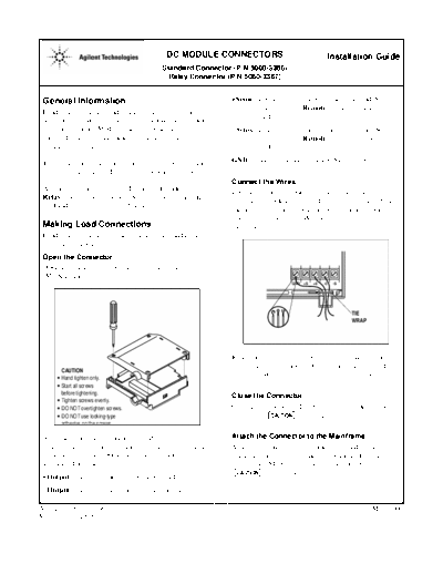
Image preview - the first page of the document

>> Download HP DC Module Connectors Installation documenatation <<
Text preview - extract from the document
                                             DC MODULE CONNECTORS                               Installation Guide
                                            Standard Connector (P/N 5060-3386)
                                              Relay Connector (P/N 5060-3387)


 General Information                                           +Sense used to connect the + remote sense lead. Set the
                                                                      sense switch to Remote when this connection is
 Load connections are made on the connector supplied
                                                                      used.
 with each module. The connector is fastened to the back
 of the mainframe. Modules can then be installed or            -Sense used to connect the - remote sense lead. Set the
 removed from the mainframe without disturbing the                    sense switch to Remote when this connection is
 wiring on the connector.                                             used.

 The connector has a switch to select either local or remote   GND      used for signal ground (GND) connections.
 voltage sensing, depending on how the load is connected.
                                                               Connect the Wires
 A relay connector is identified by a check mark on the        Loosen the barrier block screws and connect the wires.
 Relay label on the connector. Relay connectors include        The barrier block accepts spade or ring terminals. You
 load and sense disconnect and polarity reversal relays.       can also connect a stripped wire to the barrier block.
                                                               Twist the wire around under the screw terminal and
 Making Load Connections                                       tighten the screw.
 Load connections are the same on both the standard and
 the relay connector.
 Open the Connector
 Open the connector by loosening the four corner screws
 (M3 X 10 mm).


                                                                                                         TIE
                                                                                                         WRAP


                                                               Route the wires out of the bottom of the connector as
                                                               shown in the figure above. Use the tie-wrap supplied
        CAUTION
◦ Jabse Service Manual Search 2024 ◦ Jabse Pravopis ◦ onTap.bg ◦ Other service manual resources online : Fixya ◦ eServiceinfo