Service Manuals, User Guides, Schematic Diagrams or docs for : BOSE Audio AV-3-2-1 SM 270000-SM_rev2_pages50-58
<< Back | HomeMost service manuals and schematics are PDF files, so You will need Adobre Acrobat Reader to view : Acrobat Download Some of the files are DjVu format. Readers and resources available here : DjVu Resources
For the compressed files, most common are zip and rar. Please, extract files with Your favorite compression software ( WinZip, WinRAR ... ) before viewing. If a document has multiple parts, You should download all, before extracting.
Good luck. Repair on Your own risk. Make sure You know what You are doing.
Image preview - the first page of the document

>> Download 270000-SM_rev2_pages50-58 documenatation <<
Text preview - extract from the document
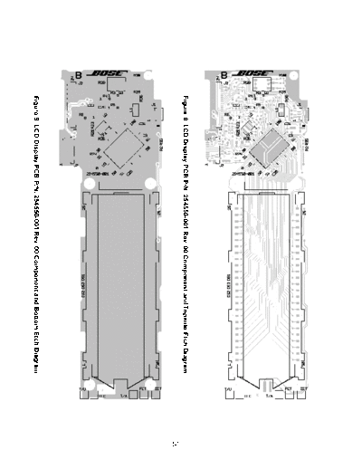
Figure 8. LCD Display PCB P/N: 254550-001 Rev. 00 Component and Topside Etch Diagram


                                                                                       50
Figure 9. LCD Display PCB P/N: 254550-001 Rev. 00 Component and Bottom Etch Diagram
Figure 10. LCD Display PCB P/N: 254550-001 Rev. 01 Component and Topside Etch Diagram


                                                                                        51
Figure 11. LCD Display PCB P/N: 254550-001 Rev. 01 Component and Bottom Etch Diagram
Figure 12. LCD Display PCB P/N: 254550-001 Rev. 02 and 03 Component and Topside Etch Diagram


                                                                                               52
Figure 13. LCD Display PCB P/N: 254550-001 Rev. 02 and 03 Component and Bottom Etch Diagram
                                                                                          53
Figure 14. Bass Amplifier PCB P/N: 254574-001 Rev. 00 Component and Etch Layout Diagram
                                                                                                             54
                                                                 Note: PCB P/N: 266469-001 also has solder
                                                                 pads for C26 located next to C22.
Figure 15. Bass Amplifier PCB P/N: 254574-001 Rev. 01 Component and Etch Layout Diagram
           Bass Amplifier PCB P/N: 266469-001 Rev. 00 Component and Etch Layout Diagram
                                                                                          55
Figure 16. Bass Amplifier PCB P/N: 266469-001 Rev. 01 Component and Etch Layout Diagram
                                                                                          56
Figure 17. Bass Amplifier PCB P/N: 268858-001 Rev. 00 Component and Etch Layout Diagram
                               GLOSSARY OF TERMS
Aspect Ratio - The shape of the rectangular picture in a TV set. It is the width of the picture relative
to the height. Our standard TV picture, is 4 units wide by 3 units high, or 4:3 in aspect ratio. There
are currently two standard TV aspect ratios in the U.S., 4:3 and 16:9.

Chapter - In DVD-Video, a division of a title. Technically called part of a title (PTT).

Component Video - A video system containing three separate color component signals, either red/
green/blue (RGB) or chroma/color difference (YPbPr), in analog or digital form. The MPEG-2 en-
coding system used by DVD is based on color-difference component digital video.

Composite Video - A single video signal that contains luminance, color and synchronization infor-
mation. NTSC and PAL are examples of composite video systems.

Dolby Digital
◦ Jabse Service Manual Search 2024 ◦ Jabse Pravopis ◦ onTap.bg ◦ Other service manual resources online : Fixya ◦ eServiceinfo