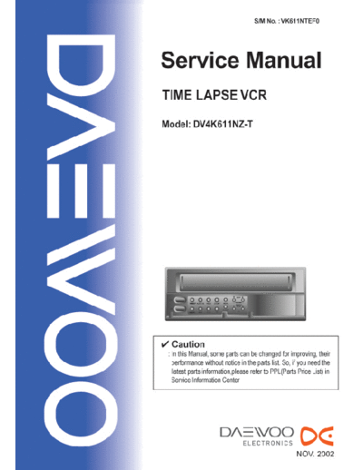
Service Manuals, User Guides, Schematic Diagrams or docs for : Daewoo Video-DVD DAEWOO_DV4K611NZ-T_TIME_LAPSE_VCR
<< Back | HomeMost service manuals and schematics are PDF files, so You will need Adobre Acrobat Reader to view : Acrobat Download Some of the files are DjVu format. Readers and resources available here : DjVu Resources
For the compressed files, most common are zip and rar. Please, extract files with Your favorite compression software ( WinZip, WinRAR ... ) before viewing. If a document has multiple parts, You should download all, before extracting.
Good luck. Repair on Your own risk. Make sure You know what You are doing.
Image preview - the first page of the document

>> Download DAEWOO_DV4K611NZ-T_TIME_LAPSE_VCR documenatation <<
Text preview - extract from the document
TABLE OF CONTENTS
SAFETY&PRECAUTIONS ............................................................................................... 2
EXTERNAL VIEWS ........................................................................................................ 4
 FRONT VIEWS FUNCTION ...................................................................................................................4
 REAR VIEWS FUNCTION .....................................................................................................................5

ELECTRICAL ADJUSTMENT ........................................................................................... 6
SPECIFICATIONS ....................................................................................................... 7
TIMELAPSE REC/PB SPEED CHART ................................................................................ 9
CIRCUIT OPERATION .................................................................................................. 10
RS-232C .................................................................................................................... 15
TROUBLE SHOOTING FLOW CHART ............................................................................. 27
 POWER CIRCUIT ................................................................................................................................27
 SERVO-SYSCON CIRCUIT ...................................................................................................................29

u-COM PORT DESCRIPTION ....................................................................................... 38
VOLTAGE CHART ....................................................................................................... 41
CIRCUIT DIAGRAM ..................................................................................................... 45
 CONNECTION DIAGRAM ..................................................................................................................45
 POWER CIRCUIT DIAGRAM ................................................................................................................46
 SYSCON CIRCUIT DIAGRAM ..............................................................................................................47
 A/V CIRCUIT DIAGRAM ......................................................................................................................48
 OSD CIRCUIT DIAGRAM ....................................................................................................................49
 LOGIC CIRCUIT DIAGRAM .................................................................................................................50
 TERMINAL CIRCUIT DIAGRAM ............................................................................................................51

COMPONENTS LOCATION GUIDE ON PCB BOTTOM VIEW ........................................... 52
 PCB MAIN .........................................................................................................................................52
 PCB LOGIC ......................................................................................................................................53
 PCB JACK .........................................................................................................................................54

DISASSEMBLY ............................................................................................................. 55
 PANEL FRONT ASS' ...........................................................................................................................55
                   Y
 SET TOTAL ASS' .................................................................................................................................56
              Y
 PACKING ASS' .................................................................................................................................57
              Y

ELECTRICAL PARTS LIST ............................................................................................... 58


                                                                                 1
 SAFETY&PRECAUTIONS
SAFETY CHECK AFTER SERVING

Examine the area surrounding the repaired location for damage or deterioration. Observe that screw,
parts and wires have been returned to original positions. Afterwards, perform the following tests and con-
form the specified values in order to verify compliance with safety standards.

1. Insulation resistance test
  Confirm the specified insulation resistance between power cord plug prong and externally exposed
  parts of the set (RF terminals, antenna terminals, video and audio input and output terminals, micro-
  phone jacks, earphone jacks, etc.) is greater than values given in table 1 below.

2. Dielectric strengthen test
  Confirm specified dielectric strengthen between
  power cord plug prongs and exposed accessible parts
  of the set (RF terminals, antenna terminals, video and
  audio input output terminals, microphone jack, ear
  phone jacks, etc.) is greater than values given table 1.

3. Clearance distance
  When replacing primary circuit component, confirm specified clearance distance (d), (d') between sol-
  dered terminals, and between terminals and surrounding metallic parts. See table below.

  Rating for selected areas

                                                 Insulation              Dielectric            Clearance
  AC Line Voltage             Region
                                                 Resistance              Strength            Distance(d),(d)
        100V                  Japan            ] 1M/500V DC             1kV AC 1min.                ]3
     110 to 130V         USA & Canada                  -               900V AC 1min.               ] 3.2
                             Europe                                                                ] 6(d)
    * 110 to 130V
                            Australia         ] 10M/500V DC             4kV AC 1min.               ] 8(d')
     200 to 240V
                          Latin America                                                       (a :Power cord)

* : Class model only


NOTE
    This table is unofficial and for reference only. Be sure to confirm the precise values for your particular


                                                           2
                                                                                    SAFETY&PRECAUTIONS


4. Leakage current test
  Confirm specified or lower leakage current between
  B(earth ground, power cord plug prongs) and externally
  exposed accessible parts (RF terminals, antenna termi-
  nals, video and audio input output terminals, microphone
  jacks, earphone jacks, etc.)
  Measuring method:(Power ON) Insert load Z between
  B(earth ground, power cord plug prongs) and exposed
  accessible parts. Use on AC voltmeter to measure across both terminals of load Z. See figure2 and
  following table.

  Leakage current ratings for selected are as

 AC Line Voltage       Region               Load Z             Leakage Current(i)   Clearance Distance(d),(d'
                                                                                                            )

      100V             Japan                                      i*1mArms          Exposed accessible parts
                                             1k

                     USA &Can-                     15k
◦ Jabse Service Manual Search 2025 ◦ Jabse Pravopis ◦ onTap.bg ◦ Other service manual resources online : Fixya ◦ eServiceinfo