Service Manuals, User Guides, Schematic Diagrams or docs for : Daewoo Video DV-K221DY vq-253
<< Back | HomeMost service manuals and schematics are PDF files, so You will need Adobre Acrobat Reader to view : Acrobat Download Some of the files are DjVu format. Readers and resources available here : DjVu Resources
For the compressed files, most common are zip and rar. Please, extract files with Your favorite compression software ( WinZip, WinRAR ... ) before viewing. If a document has multiple parts, You should download all, before extracting.
Good luck. Repair on Your own risk. Make sure You know what You are doing.
Image preview - the first page of the document
>> Download vq-253 documenatation <<
Text preview - extract from the document
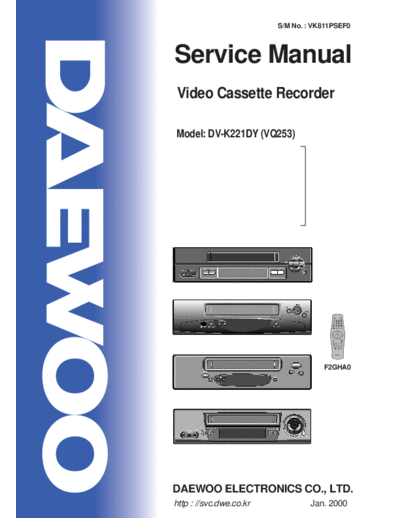
                         S/M No. : VK811PSEF0


Service Manual
Video Cassette Recorder

Model: DV-K221DY (VQ253)


                                          A


                                     F2GHA0


DAEWOO ELECTRONICS CO., LTD.
http : //svc.dwe.co.kr            Jan. 2000
 ELECTRICAL ADJUSTMENT
1. PLAYBACK PHASE


                               ADJUSTMENT                                      TEST          TEST        INPUT
      ITEM         MODE                              CHECK POINT
                                  POINT                                      EQUIPMENT       TAPE       SIGNAL
     6.5H                                            PIN 4 & PIN 5
                    PLAY       [REC] BUTTON                                 OSCILLOSCOPE     DP-2     NO SIGNAL
 ADJUSTMENT                                            OF P504


                        ADJUSTMENT PARTS                                             MEASURING POINT
 PCB : MAIN - TOP VIEW
               TMI                                                            OSCILLOSCOPE
               BLOC
                                PRE-
                                AMP                                           CH1     CH2

                                                                                                    PATH JIG
                 P50


                                     TO PATH JIG


ADJUSTMENT PROCEDURE

1. Play back the test tape. (DP-2)

2. Set the oscilloscope to the CHOP mode. Connect CH1 to the SW PULSE (PIN 4 of P504)

3. Connect CH2 to the ENVE signal (PIN5 of P504)

4. Insert PATH JIG and press "REC" button on the remote control.

5. Check the position of the V-sync from the rising edge of the SW pulse.
  (Standard : 6.5H
◦ Jabse Service Manual Search 2024 ◦ Jabse Pravopis ◦ onTap.bg ◦ Other service manual resources online : Fixya ◦ eServiceinfo