Service Manuals, User Guides, Schematic Diagrams or docs for : Fluke 5x-2 datasheets 74HC_HCT4052
<< Back | HomeMost service manuals and schematics are PDF files, so You will need Adobre Acrobat Reader to view : Acrobat Download Some of the files are DjVu format. Readers and resources available here : DjVu Resources
For the compressed files, most common are zip and rar. Please, extract files with Your favorite compression software ( WinZip, WinRAR ... ) before viewing. If a document has multiple parts, You should download all, before extracting.
Good luck. Repair on Your own risk. Make sure You know what You are doing.
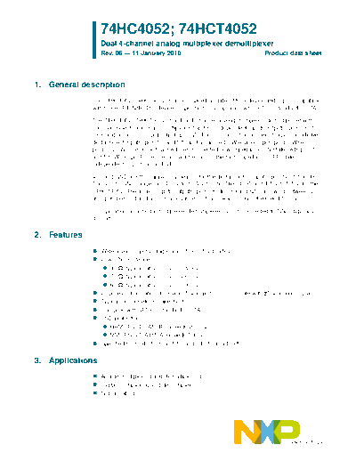
Image preview - the first page of the document

>> Download 74HC_HCT4052 documenatation <<
Text preview - extract from the document
                  74HC4052; 74HCT4052
                  Dual 4-channel analog multiplexer/demultiplexer
                  Rev. 06 -- 11 January 2010                                      Product data sheet


1. General description
              The 74HC4052; 74HCT4052 is a high-speed Si-gate CMOS device and is pin compatible
              with the HEF4052B. The device is specified in compliance with JEDEC standard no. 7A.

              The 74HC4052; 74HCT4052 is a dual 4-channel analog multiplexer/demultiplexer with
              common select logic. Each multiplexer has four independent inputs/outputs (pins nY0 to
              nY3) and a common input/output (pin nZ). The common channel select logics include two
              digital select inputs (pins S0 and S1) and an active LOW enable input (pin E). When
              pin E = LOW, one of the four switches is selected (low-impedance ON-state) with pins S0
              and S1. When pin E = HIGH, all switches are in the high-impedance OFF-state,
              independent of pins S0 and S1.

              VCC and GND are the supply voltage pins for the digital control inputs (pins S0, S1 and E).
              The VCC to GND ranges are 2.0 V to 10.0 V for the 74HC4052 and 4.5 V to 5.5 V for the
              74HCT4052. The analog inputs/outputs (pins nY0 to nY3 and nZ) can swing between VCC
              as a positive limit and VEE as a negative limit. VCC - VEE may not exceed 10.0 V.

              For operation as a digital multiplexer/demultiplexer, VEE is connected to GND (typically
              ground).


2. Features
                  Wide analog input voltage range from -5 V to +5 V
                  Low ON resistance:
                     80  (typical) at VCC - VEE = 4.5 V
                     70  (typical) at VCC - VEE = 6.0 V
                     60  (typical) at VCC - VEE = 9.0 V
                  Logic level translation: to enable 5 V logic to communicate with
◦ Jabse Service Manual Search 2024 ◦ Jabse Pravopis ◦ onTap.bg ◦ Other service manual resources online : Fixya ◦ eServiceinfo