Service Manuals, User Guides, Schematic Diagrams or docs for : HP Publikacje 5989-4840EN
<< Back | HomeMost service manuals and schematics are PDF files, so You will need Adobre Acrobat Reader to view : Acrobat Download Some of the files are DjVu format. Readers and resources available here : DjVu Resources
For the compressed files, most common are zip and rar. Please, extract files with Your favorite compression software ( WinZip, WinRAR ... ) before viewing. If a document has multiple parts, You should download all, before extracting.
Good luck. Repair on Your own risk. Make sure You know what You are doing.
Image preview - the first page of the document
>> Download 5989-4840EN documenatation <<
Text preview - extract from the document
Specifying Calibration Standards
and Kits for Agilent Vector
Network Analyzers
Application Note 1287-11
Table of Contents Introduction ................................................................................................................................. 3
Measurement errors ................................................................................................................ 3
Measurement calibration ....................................................................................................... 3
Calibration Kits .......................................................................................................................... 4
Connector definitions .............................................................................................................. 5
Calibration standards definition ............................................................................................ 6
Class assignment ................................................................................................................... 14
Modification Procedure ........................................................................................................ 22
PNA calibration kit entry/modification procedure .......................................................... 23
8510 Calibration kit modification/entry procedure ......................................................... 27
Appendix A: Dimensional Considerations in Coaxial Connectors .......................... 30
7-mm coaxial connector interface ...................................................................................... 30
3.5-mm, 2.4-mm, 1.85-mm, 1.0-mm coaxial connector interface .................................. 30
Type-N coaxial connector interface ................................................................................... 31
Appendix B: Derivation of Coaxial Calibration Coefficient Model..................... 32
Appendix C1: Derivation of Waveguide Calibration Coefficient Model........... 35
Appendix D: Data-based Calibration Standard Definition File Format ............ 39
Example file ............................................................................................................................. 39
Preliminary #PNA keywords ............................................................................................... 40
References ................................................................................................................................. 41
Web Resources ........................................................................................................................ 42
2
Introduction Measurement errors
Measurement errors in network analysis can be separated into two categories: random
and systematic errors. Both random and systematic errors are vector quantities. Random
errors are non-repeatable measurement variations and are usually unpredictable.
Systematic errors are repeatable measurement variations in the test setup.
Systematic errors include impedance mismatch, system frequency response and leakage
signals in the test setup. In most microwave measurements, systematic errors are the
most significant source of measurement uncertainty. The source of these errors can be
attributed to the signal separation scheme used.
Numerous publications are available on vector network analyzer (VNA) calibration
techniques. References [1], [2], [3], [4], [5], [6], [7] and [8] are just some of the pub-
lished work. Agilent's application notes: 1287-1, 1287-2 and 1287-3 also provide insights
on VNAs and VNA error correction. It is recommended that a user be familiar with these
calibration techniques and terminologies to get the maximum understanding from this
application note.
Measurement calibration
A measurement calibration is a process which mathematically derives the systematic
error model for the VNA. This error model is an array of vector error coefficients used to
establish a fixed reference plane of zero phase shift, zero reflection magnitude, lossless
transmission magnitude and known impedance. The array of coefficients is computed
by measuring a set of "known" devices or calibration standards connected at a fixed
measurement plane.
Different calibration techniques are used to solve different error models. The definition
of calibration standards and types are set up differently for the applicable calibration
techniques. Solving the full 2-port twelve term error model using the short/open/ load/
thru (SOLT) calibration method is an example of only one of the many measurement
calibrations available.
The type of measurement calibration selected by the user depends on the device to
be measured (i.e., 1-port or 2-port device) the calibration standards available and the
extent of accuracy enhancement desired. A combination of calibrations can be used in
the measurement of a particular device, such as adapter removal calibration for non-
insertable devices. The accuracy of subsequent device measurements depends on the
accuracy and stability of the test equipment, the accuracy of the calibration standard
model, and the calibration method used in conjunction with the error correction model.
This application note covers calibration standard definitions, calibration kit content and
its structure requirements for Agilent's vector network analyzers. It also provides some
examples of how to set up a new calibration kit and how to modify an existing calibra-
tion kit definition file.
3
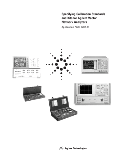
Calibration Kits A mechanical calibration kit consists of a set of physical devices called standards, as
shown in Figure 1. Each standard has a precisely known magnitude and phase response
as a function of frequency. In order for the VNA to use the standards of a calibration kit,
each standard must be "assigned" or organized into standard classes which correspond
to the calibration method used by the VNA. Agilent currently supplies mechanical
calibration kits with 1.0-mm, 1.85-mm, 2.4-mm, 3.5-mm, 7-mm, and Type-N 50 ohm,
Type-N 75 ohm , Type-FD 75 ohm and 7-16 coaxial connectors. Rectangular waveguide
calibration kits include X, P, K, R, Q, U, V and W bands. Calibration for microstrip and
other non-coaxial media is described in Product Note 8510-8A: Agilent Network Analysis
Applying the 8510 TRL Calibration for Non-Coaxial Measurements, literature number
5091-3645E. A calibration kit may support many calibration methods.
Figure 1. Mechanical cal standards and cal kit
4
Connector definitions
In addition to calibration standard definitions and standard class assignments, calibra-
tion kits also provide definitions of connectors. Agilent's PNA network analyzer family
uses the connector definition to define connector (Figure 2):
◦ Jabse Service Manual Search 2024 ◦ Jabse Pravopis ◦ onTap.bg ◦ Other service manual resources online : Fixya ◦ eServiceinfo