Service Manuals, User Guides, Schematic Diagrams or docs for : HP Publikacje HP-Bench-Briefs-1973-04
<< Back | HomeMost service manuals and schematics are PDF files, so You will need Adobre Acrobat Reader to view : Acrobat Download Some of the files are DjVu format. Readers and resources available here : DjVu Resources
For the compressed files, most common are zip and rar. Please, extract files with Your favorite compression software ( WinZip, WinRAR ... ) before viewing. If a document has multiple parts, You should download all, before extracting.
Good luck. Repair on Your own risk. Make sure You know what You are doing.
Image preview - the first page of the document
>> Download HP-Bench-Briefs-1973-04 documenatation <<
Text preview - extract from the document
VOLUME 13 NUMBER 1 APRIL 1973
2
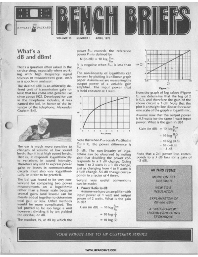
What's a power Pout exceeds the reference
power Pref is defined by
dB and dBm? N (in dB) = 10 log k
1
Pref 0
N i s negative when Pwt is less than %'
j That's a question often asked in the p, -?
service shop, especially when work-
ing with high frequency signal The non-linearity of logarithms can -2
Sources or measurement gear, such be Seen by plotting it On linear
graph
-3
as a spectrum analyzer. paper. Assume we are measuring the
output power of a variable gain
The decibel (dB) i s an arbitrarily de- amplifier. The input power (pref)
fined unit of transmission gain (or is held constant at watt.
loss) that has come into general use From the graph of log values (Figur
since about 1925.Developed for use s I , we determine that the log of 2
)
in the telephone industry, it was is 0.3, and therefore the gain of the
named the bel, in honor of the in- above circuit i s 3 dB. Note that the
ventor of the telephone, Alexander plot i s a straight line (linear) because
Graham Bell. one scale of the graph is logarithmic.
Assume now that the output power
is 0.5 watts for the same 1 watt input
power. What i s the gain in dB?
Note that when Pout equals Pref(that i
was found to be very con- Several very useful conversions
for comparing two power can be made:
r, N, of dB by which the
Y O U R PRIVATE LINE TO H P C U S T O M E R SERVIC
* I
-2
.-
:
dB AND dBm
I
I
2. dB to Power Ratio A 6 dB gain corresponds to a power 4. dB to Voltage Ratio
The above procedure can be re- change of 4:l. Verify this by calcu- The above procedure can also be re-
versed by rearranging the formula lating the power in the 2 volt and 1 versed by manipulating the formula.
and using anti-logs, the reverse of volt signals. Gain (in dB)
logs. Probably a more common use of this Since L o gInp = 20
Since log Pout - Gain (in dB)
-- equation is measuring the power -
Eout
= antilog Gain (in dB)
Pin 10 output variation in an amplifier vs. Ein 20
frequency, gain, or other parameter. or
Eout = Ein x antilog
Gain (in dB)
Assume you are testing an audio 20
Assume we have an amplifier with a amplifier for frequency response. A
1 watt input and 13 dB gain. What i s Let's assume that we want to verify
reference input level is established that a generator meets its output
the output power? at 1K Hz and a voltmeter connected specifications of a maximum devia-
-
Pout = Pin Antilog -
13 dB
10
to the output measures4.5 volts. The tion of 2 dB from the peak. The point
input signal amplitude is held con- of peak output is identified and mea-
= 1 * (antilog 1.3) stant as the frequency is varied from
= 1 (20) = 20 watts sured at 2.1 volts. What voltage cor-
20 Hz to 20K Hz. Let`s assume that responds to a 2 dB drop from 2.1
The first three examples of use of the the maximum voltage drop from the volts?
log graph are diagramed on the reference is observed at 20 Hz, with -2 dB
graph. Other values are similarly de- 3.57 volts being measured and the E = 2.1 antilog -
20
termined or can be obtained from maximum voltage rise of 5.67 volts i s = 2.1 (0.79)
log tables in reference texts. observed at 3K Hz. Calculate the = 1.66 volts
output variation in dB.
3. Voltage ratio to dB 5. Power to dBm
In many cases the measurement Gain (in dB) = 20 log VI
- All of the above are relativemeasure-
Vref
made is in voltage, not power, since ments. The dBm is an absolute mea-
voltage measuring instruments are Drop (in dB) = 20 log 35 .7 surement because it i s referenced
often more available than power 4.5 to a power level of 1 mw. This means
measuring meters. It may be con- = 20 log (0.80) that 1 mw = 0 dBm, which is true
venient to know the signal level in = 20 (-0.10) regardless of the impedance of the
dB and the formula can be adapted = -2.0 dB system. Going back to the power
to this measurement, since power
Rise (in dB) = 20 log 5.67
- ratio formula, let`s substitute 1 mw
- E2 4.5 for Pref.
-ir = 20 log (1.26) Absolute power level (in dBm) =
= 20 (0.100)
Gain (in dB) = 10 l o gPout
p, 10 log - Pout
= 2.0 dB 1 mw
jEout)'
Rout Therefore, at the given power level, Assume that an amplifier has an out-
= 10 log
(Ein)' this amplifier has a +2 dB response put of 4 mw. What is the output level
Ein from the 1 K Hz reference. Other in dBm?
If the input and output impedances problems of this type can be similarly Absolute- (in dBm) = 10 log 4 mw
-
are made up of equal resistances, calculated. level 1 mw
this simplifies to = 10 log (4)
A common, but technically incorrect,
Eout ' usage of dB.i s expressing the voltage
= 10 (0.6)
Gain (in dB) = 10 log in . = 6 dBm
Another mathematical rule transfers #In of a C ' r U l t : wthnut regard
impedance. For example, an ampli- Another amplifier has an input lev>-
the squared term to the coefficient, fier with an input impedance of 10K of +4 dBm and an output of 0.02
yielding ohms and an output impedance of watts. What i s the gain of the am-
Gain (in dB) = 20 log Eout 1K ohms may require a 10 mv input plifier?
Ein
to develop 1 volt at the output. In- Let's first calculate the output level
It is important to note that the above serting 1 volt and 10 mv in the for- in dBm, noting that 0.02 watts equals
i s true only for equal impedances. mula above yields a gain of 40 dB. 20 milliwatts.
Let's assume we have an amplifier It i s important to note that this i s the
Absolute Level (in dBm)
which supplies a 2 volt output for a voltage gain and not the power gain. = 10 log-20 mw
1 volt input. The input and output The correct definition of dB i s the
impedances are equal. What i s the ratio of two power levels. = 10 log 20
gain in dB? Use the voltages and impedances = 10 (1.3)
2v above to calculate input and output = 13 dBm
Gain (in dB) = 20 log -
Iv power, then use the formula #I An output of 13 dBm and an input
= 20 log (2) above to determine true dB gain. Do of 4 dBm gives a gain of 9 dB. Note
= 20 (0.3) = 6 dB you get 50 dB? that the input and outputs are abso-
VVVVVV HPARCHIVF COM
t
1.
= ~
HELP FROM POLAROIDITO-3 INSULATOR
'I
, Read power ratio on the display NEED ASSISTANCE
To obtain actual power reading:
ive measurement. Punch in reference powerIp WITH
1617)
Read power on display TRACE
equation can be trans- 3- VOhW Ratio to de: RECORD1NG? 5176
conversion of dBm Punch in voltage reading
Punch in reference voltage read- If you use an oscilloscope camera
ing.m I B
P am
Read dB on display
to record waveforms, you can now
" free technical assistance bv tele-
get
4. dB to Voltage R;r% phone from Polaroid Corporahon.
Punch in dB
How many watts correspond to a m m
m Trained technical experts will accept
all calls, including COLLECT calls,
power level of +30 dBm? m@Im from any point in the continental
-
P (in mw) = (1) antilog 30- Read voltage ratio on display
To obtain voltage reading:
United States. They can assist you
10 with photographic techniques and
= antilog 3 = la00 Punch i n reference voltage read-
problems, or recommend hardware
Power = 1 watt ing 0 to mate a particular camera/oscillo-
Read voltage on display scope combination.
There exist zero references other 5. Power to dBm:
than 1 mw. A dBV is defined using Polaroid's Technical Assistance Line
one volts as the reference level. Punch in power reading (in
milliwatts) I i @ 0
) 3
J -(617) 547-5176 provides rapid ac-
Audio experts will be familiar with cess to information, without charge,
dBA, where a standard sound level 6. dBmtomw: to users of Polaroid's industrial
is used as a reference. Some high Punch in dBm cameras and instant-developingfilms
power areas use dBk, which is a mea- mlamDEl@m in a wide variety of disciplines. This
surement referenced to one kilowatt. Read power (in milliwatts) on service is available any weekday,
display. except holidays, from 9:OO a.m. to
While other methods of reference
exist for absolute levels, using dBm The graph on page 7 may be helpful 5:OO pm., Eastern Time. Customers
appears to be most common for in converting signal levels in dBm or in Canada, Europe and elsewhere
electronic measurements. watts tovolts. This conversion can be can place prepaid calls or write to
calculated for any impedance using Richard Jagolta, Polaroid Technical
A graph designed to be cut out of ohms law; several of the more Assistance, 549 Technology Square,
the issue i s included on page 7 for a common impedances are included Cambridge, Massachusetts 02139.
handy reference for voltage-dBm on the conversion chart for con-
conversion. venience of use. NEW TO-3 INSULATOR
Precise calculations of the dBm to
voltage chart for 50 ohm and other
impedances can be obtained with
the following steps:
All of Punch in dBm readin E
the above a@Hmmobm
calculations
can be
arnmwmm
Punch in impedancem Here is something of interest if you
made on the Read voltage (in volts) on display. have ever crawled under a work-
HP 35 mini- While the HP 80 business version bench looking for a transistor in-
calculator. minicalculator does not have a m sulator dropped while changing a
function, the logarithms of a num- transistor. A one-piece insulator is
ber can be computed with the fol- available that replaces six individual
lowing sequence: pieces used in some HP products.
mmmm Two sizes are available to accommo-
1 Power ratio to dB:
. Punch in number I date various heat sink thicknesses.
Punch in 1st power level I IF
[T 1 Part number 0340-0795has shoulders
E Punch in 2.3025 El for a 3/16inch or thicker metal and is
Punch in reference power level Read log on display priced at 15 cents. For thinner
mmmm The other functions are similar. Note metals, use 0340-0503,priced at 25
Read answer on the display that the HP 80 has a I function cents.
2. dB to Power Ratio: while the HP 35 has the m. There- Having a small stock of these avail-
fore, to calculate antilogs with the able may prove economical because
HP 80, push I where the HP of the time saved when replacing
35 instructions call for a transistor.
WWW.HPARCHIVE.COM
* I
.- TROUBLE SHOOTING HINT
A "NOT-SO-NEW" not worry about in-between states! 1. The OFF state of any transistor,
Here's the method: FET, or SCR can be obtained by either
TROUBLESHOOTING Try to force the circuit to change
opening the collector or emitter (in a
case where you are not sure that the
TECHNIQUE states (opposite to whatever stage devise i s good), or shorting the
it is presently locked in) and deter- emitter base junction. Shorting the
by Dan Struckmann
mine whether or not the circuit's B-E of a transistor will cause it to turn
When your everyday techniques of reaction to the change is correct. off and the collector should float
troubleshooting seem to run you in toward the supply voltage, indicating
circles, pick up a clip lead and a 1. If the result does indeed corres-
pond with what you had initially that the transistor is at least func-
voltmeter!
1 am sure that most of us on the
bench have picked up or developed functional.
a
decided, there is a ood chance that
the active devices a er that point are
tional. In the case of an SCR or
thyristor, either disconnect the cath-
ode or anode or disconnect the gate
our own troubleshooting tech- lead. Disconnectingthe gate will also
niques. Some form of logical half- 2. If the result does not correspond show if the SCR i s shorted.
splitting with scope waveforms, with what you had initially decided,
generally one or more of the active 2. An ON state of any device is sim-
voltage checks and board substitu- ulated by shorting the emitter
tion is usually employed to trace the devices after that point are defective.
to collector, anode to cathode, or
problem down to board level. At this Continue in this manner, half- drain to source. For a transistor to be
point, how does the technician find splitting as you go along until a sim- ON, the E-B junction must be for-
the one or two defective parts in a ple circuit i s left. ward biased, which should cause a
23-transistor, direct-coupled, dual Three very important points must correspondingly low voltage drop
closed-loop monster? (A pre-regu- be stressed. First, be sure that any across the E-C junction.
lated, regulated, constant voltage, forced response you may initiate will
constant current programmable With the above in mind, do what is
not damage any other components. necessary to put the device in the
power supply fits this description). Be especially careful in high power
state you desire.
This is when the technician steps circuits such as output drivers and
back with some basic circuit logic high current power supplies. Sec- In many instances, forcing a given
and an understandingof the unit and ond, do not look for any change any response might damage other com-
narrows the region of probable cause farther along in the circuit than you ponents and caution must be exer-
to' reduce troubleshooting time. can logically justify; for example, cised. Rotating adjustment pots in
don't look for a level change in the the circuits may be used to cause a
With the knowledge of the on-off change. When this i s not possible,
characteristics of transistors, ex- output when the output stage is AC
coupled. Third, keep in mind that use your voltmeter to measure E-B
amine each stage of the circuit in and E-C to identify the defective
question to determine how each you are looking for simple responses
such as go, no-go, high or low device.
stage would function if everything
were working properly. Using this levels, etc. Now let's consider a few practical
technique, we can usually neglect The means by which you force your examples. Looking at Figure 1, you
all closed feedback loops, and need response i s as follows: will notice a differential amplifier and
W M M I HPARCHIVF CnM
[ I MULTIPLIER PREFIXES "
'I
:[
associated states, all direct-coupled. open, Q could be shorted, or the
1 METRIC MULTIPLlER
This circuit is powered by positive input level could be wrong also.
and negative supplies and it is quite So we have several possibilities, any PREFIXES
difficult, if not impossible, to deter- of which singly or in combination
could cause our problem. Just look- Here's a handy reference listing of
mine either correct voltage levels or all the multiplier prefixes currently
the logic state of a device. It may be ing at voltage levels many times leads
to confusion. The clip lead technique being used. This may prove helpful
noted also that this type of circuitry
lends itself very nicely here because when working with unfamiliar units
usually has one or more feedback
it gives us definite good/bad ans- or trying to determine conversions,
loops tied in. Let's assume that the such as how many nano seconds are
voltage at Point B is negative with wers, with no guess work! That is,
in one microsecond. Or what is the
respect to Point A (which is incorrect) we do not have to guess what all the
inputs or outputs may be, because capacitance in microfarads of a IO00
and we want to determine the cause. picofarad capacitor.
Applying the method described we can make the inputs or outputs
earlier, determine first that forcing look like we want them to. Many Of course some of us who have
Point B positive will not destroy any times knowing what they are gives us been around awhile will recognize
following circuitry. Next determine a no information. In the case above, the picofarad (which is farad)
good point to "half-split" the circuit. we could short E-B of Q which1 used to be called micro micro farad,
Let's choose the collector of QIA. should make the collector of Q go1 and this is a good clue.
Determine what state QIA must be high. This should turn on 42, caus-
in to force 4 3 "on," thus pulling ing i t s collector to go low. Again,
Point B positive. A glance tells us given only the Q 2 collector was
that QIA must be turned on. So, high, we could tell whether or not
let's simulate that by using a clip lead 4 2 was bad without making any
to connect the emitter of QIA to other voltage measurements. You
i t s collector. If the level at Point B have probably discovered that a
does not change, we know that feedback system is difficult to repair
either 4 3 or Q16 is bad. Point C is because there are so many variables
positive and the circuitry at or before to consider when trying to decide
Q is probably good (neglecting
1 what is happening. Do you want to test yourself?
more obvious power supply prob- The suggested approach is to force a 7. How manynanosecondsare inone
lems at this point). transistor or other active element to microsecond?-
If point B had gdne positive instead, some state. Then we know if the next 2. A electronic frequencycounter has
we would have known that Q or the
1 element i s doing what it is supposed displayedameasurementof7.4532
circuitry before Q had failed. The
1 to be doing, which is much better GHz. What is this reading in KHz?
same technique i s used to continue than guessing if the output is correct
the isolation process. after looking at all the inputs. With
the complexity of instruments and 3. What i s the capacitance in micro-
This technique is especially valuable farads o f a 7000 pf capacitor?
in closed loop systems (or any circuit systems today, the technician i s not
with feedback) because it gives a afforded the luxury of guessing!
known input to a stage and a given With a little practice and some in- 4. One inch equals 2.540 cm How
output reaction can be expected. The genuity (one experienced technician many millimeters is this? -
loop can be traversed in the forward uses a desoldering tool instead of a
or reverse direction, verifying the clip lead), a "not-so-new" tool may
Answers to Metric Multiplier Quiz
proper operation of each stageTuntil b e added to your trade techniques.
the defective stage is identified. It is the extra speed and expertise
An example of a simple feedback cir- gained by using techniques like this
cuit is given below in Figure 2. that separate the outstanding repair-
man from the average technician and
keep him growing with the tech-
nology.
OUTPUT Dan Struckmann is a technician currently
working in the computer peripherals
INWT design laboratory at the Cupertino Divi-
sion of Hewlett-Packard. Dan joined HP
in 1971 and worked at the'corporate
customer repair center in Mountain
v- v- v-
View. Besides finding time for ham radio,
radio-controlled airplanes, and stereo,
Let's assume the voltage at the COl- Dan is attendingsan JoseState University
lector of 4 2 is higher than specified. working on a degree in electrical engi-
What could cause this? 4 2 could be neering.
WWW.HPARCHIVE.COM
* I
.- FE T CHECK E Ri UN G RO UN D E D CHASSIS
MOR Several of you asssced. about a
circuit for the square wawe genera-
ON FET tor, and here is one idea. Most
oscil have a 10 volt P to P
CHECKER squa calibration signal, but
on many oscilloscopes it is often
negative going and clamped $0
b y George Stanley ground. We need it DC coupled
and swingin around zero. You can
Oops!, is our face red, You may
have noticed in `the November issue
%
use a 5 volt attery or power supply
to move it up, but that's a bit awk-
(Vol. 12, No. 4) that there was an ward. Figure 5 shows a more novel
error in Figure 4, the FET Tester. approach.
Shown below i s the way the figure
should have been. The idea here is filter the square If any of you have any other ideas,
wave to obtain -5 VDC, and then send them in and 1'11 pass them
use this voltage as an offset voltage. along. I'm still looking for a simple
The on1 drawback is that you need square wave circuit that puts out a
L
a two< annel oscilloscope that is
capable of presentingan A-B display.
DC coupled 10 volt square wave
centered at zero.
CORRECTED
ov-
Here is a tip p u probably figured
out for yourself. In order to obtain
the waveforms shown in Table 2,
-10v -
Page 2, of the November issue, you
must have your oscilloscope DC
coupled.
UNGROUNDED CHASSIS power line noise out of the genera- conductor makes contact before
tor, but it also places a 6OV rms the ground conductor, the capaci-
ARE DANGEROUS signal on the chassis! This is 169V tors get discharged through the
p-p (relative to earth ground). input circuitry. Oqen the damage
specification is exceeded and the
input circuitry is destroyed.
12W RYS TO EARTH
QROUND
Another problem becomes evident
when the operator places one hand
on the ungrounded chassis and the
other on a grounded chassis. The
ZERO VOLTS TO EARTH 169V p-p signal may prove to be
QROUND StNCE TmS
I THE NEUTRAL
S too much of a jolt!
Why does an ungrounded signal The danger of an ungrounded signal
source pose a threat to an input The capacitors act as an A-C divider source damaging other instruments
circuit? This is the question some- network, since one side of the line and injuring personnel can also be
times asked after the input circuitry i s at ground potential. The chassis alleviated with a three-wire line cord,
to a counter or other instrument has thus has a 169V p-p 60 Hz signal so the chassis is connected to earth
been destroyed. on it. ground.
Some companies sell inexpensive This may cause no problem when The above comments also apply to
signal generators that do not use a the counter is connected to this instruments (including HP) where a
three wire tine cord, which means signal source if the ground connec- three-wire cord exists, but the third
that the chassis is not connected to tions on the input connector make wire is not grounded. If you must
earth ground. Generally, each side contact before the center conductor. use a three-wire to two-wire NEMA
of the power line will be connected The charges on the two capacitors adaptor (sometimes called a suicide
*
to chassis with a small capacitor, get shunted through the ground plug), be certain that the green
typical 0.1 pF. This helps keep circuit on the counter. If the center connects to a good ground.
WWW.HPARCHIVE.COM
dBm T O VOLTAGE CONVERSION 1
il' * ' :r
* I
dBm TO VOLTAGE CONVERSION
+40 10
watts
+30 1
+20 100
+10 mllllwatts
10
(lo-* watts)
0 1
-10 100
-20 10 microwatts
($o-~watts)
-30 1
paIHIER
-40 100
m
nano watts
- 50 10
(10-9 watts)
-80 1
- 70 100
plco watts
- 80 10
(lo-'* watts)
-90 1
-100 100
femto watts
(10-l~
watts)
-110 10
-120
a
1 pv 10 pv 100 pv 1 mv 10 mv 100 mv 1v 10 v
VOLTAGE
To convert dBm to voltage, move to the right from the dBm scale to the line
representing the impedance of the circuit being measured. Then move down
and read the signal strength on the voltage scale. Use the reverse procedure
to convert voltage to dBm. m
H E W L E T T PACKARD
~
A power scale has also been provided to allow conversion from voltage to
power or dBm to power. Note that the relationship between power and dBm 6iNCH 6RliP
does not depend on circuit impedance. APRIL 1973
For example, -30 dBm (which is 1 microwatt for all impedances) is 7mv for a
50Q impedance, but it is a 24 mv for a 600Q impedance.
WWW.HPARCHIVE.COM
-
* I
.- RECOMMENDED READING
◦ Jabse Service Manual Search 2024 ◦ Jabse Pravopis ◦ onTap.bg ◦ Other service manual resources online : Fixya ◦ eServiceinfo