Service Manuals, User Guides, Schematic Diagrams or docs for : HP Publikacje HP-Bench-Briefs-1978-05-10
<< Back | HomeMost service manuals and schematics are PDF files, so You will need Adobre Acrobat Reader to view : Acrobat Download Some of the files are DjVu format. Readers and resources available here : DjVu Resources
For the compressed files, most common are zip and rar. Please, extract files with Your favorite compression software ( WinZip, WinRAR ... ) before viewing. If a document has multiple parts, You should download all, before extracting.
Good luck. Repair on Your own risk. Make sure You know what You are doing.
Image preview - the first page of the document
>> Download HP-Bench-Briefs-1978-05-10 documenatation <<
Text preview - extract from the document
c
., .
I .
I ?
.,
:
Lii , ,
MAY-OCTOBER 1978
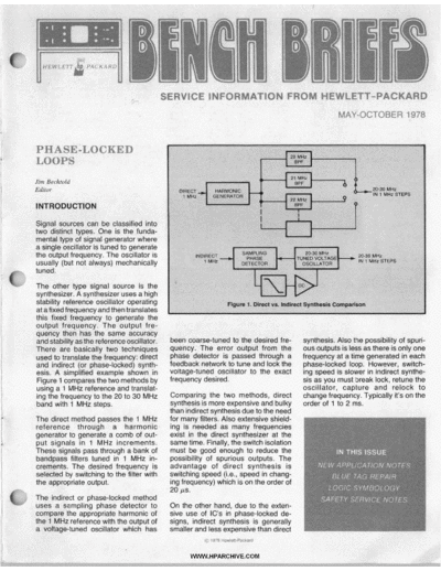
frequency desired.
oscflator, capture and weiock to
the two methods, chaagefrequemy. TypitxtMy it's on #Fe
more expensive and ~ o f l t 0 2 m .
587118 time. RWy, the swkh ierolation
pass through a bank of must be good enough t reduce ttw
o IN THIS ISSUE
w tuned in 1 Mwt in- pOSSb&j& Of SpUfiOUS Wm&. The
NEW APPLICATION NOTES
d&red frequency is direct synthesis is
BLUE TAG REPAIR
LOGIC SYMBOLOG'I
SAFETY SERVICE NOTES
On the other hand, due t the exten-
o
. . .
. ,. . *
. , .
@ 1878 Hwka-P.dud
WWW.,H PARCHIVE.COM
PHASE-LOCKED LOOP
PRINCIPLE
with no reference signal input, the
VCO will oscillate at a fixed frequency
determined by the design of the loop
locked. In fact. the lowoass filter volt-
age is the demodulated output when
the incoming signal is frequency mod-
a
Now that you understand the why of (fc). This is an important point to note: ulated (provided the controlled oscil-
phase-locked loops, let's examine the the VCO will produce an output even if lator has a linear voltage-to-frequency
how. The classic definition of a phase- the loop isn't locked. If the 10 MHz transfer characteristic). The syn-
locked loop (PLL) is a feedback sys- signal is now applied to the phase de- chronous reception of radio signals
tem whose function is to force a tector's reference input in our exam- using PLL techniques was described
voltage-controlled oscillator (VCO) to ple, and the VCO is leading in phase in the early thirties as the "homodyne"
be coherent with a certain frequency. relative to the reference input, the receiver.
By "coherent", we mean highly corre- phase detector/loop filter will respond
lated in both frequency and phase. Another way of describing the opera-
by supplying a voltage to the VCO tion of the PLL is to observe that the
There are many variations of phase- such that the VCOs output frequency phase detector is actually a mixer cir-
locked loops, but an elementary loop will decrease. As the VCOs frequency cuit that mixes the input signal with the
consists of a phase detector, low-pass lowers, the phase lag between the ref- VCO signal. This mix produces the
filter and voltage-controlled oscillator erence input and the VCO will de- sum and difference frequencies (fi+fo)
shown in Figure 2. crease until the PLL is locked. This is shown in Figure 2. When the loop is in
lock, the VCO duplicates the input
frequency so that the difference fre-
quency component (fi-fo) is zero, and
the output of the phase comparator is
a dc value proportionate to the phase
difference. The low-pass filter
removes the sum frequency compo-
nent (fi+fo), but passes the dc com-
ponent which is fed to the VCO.
-
LOOP OPERATION The frequency shown more clearly in the timing dia-
at which the VCO oscillates is deter- gram of Figure 3. Once in lock, the LOCK AND CAPTURE - The range
mined by the control voltage applied to VCO frequency is identical to the input of frequencies over which the PLL can
its input. The frequency range over signal except for a finite phase differ- track an input signal is defined as the
which the VCO can be tuned and the ence, This net phase difference is "lock range" of the system (refer to
relationship between control voltage necessary to generate the corrective Figure 4). The band of frequencies
and output frequency are determined error voltage (vd) to shift the VCO fre- over which the PLL can acquire lock
by the design of the VCO. The phase quency from its free-running value to with an incoming signal is known as
detector compares the phase differ- the input signal frequency (fi) and, the `'capture range" of the system is
ence between the input reference sig- thus, keep the PLL in lock. This self- never greater than the lock range.
nal and the output of the VCO, then correcting ability of the system also Stated another way, the PLL can track
generates a voltage (or current) pro- allows the PLL to track the frequency or maintain lock on an input signal be-
portional to the error. The phase error changes of the input signal once it is yond the capture range. Note that the
voltage is passed through a low-pass
filter which suppresses noise and any
high frequency signal components. If
the phase changes, indicating the
incoming frequency is changing, the
phase detector output voltage
increases or decreases just enough to
keep the oscillator frequency the same
as the incoming frequency. The action
of the loop then, is to slew the fre-
% quency of the VCO until the phase
error is at a steady dc value and the
two frequencies "track."
Looking a little closer at the action of
the loop, assume that the input refer-
ence is a 10 MHz signal from a very
stable source. We want to produce a
10 MHz signal which is the same fre-
quency as the 10 MHz reference. With
the loop connected as in Figure 2 but
* ..
,WWW.HPARCHlVE.COM
track with a fixed (or programmable)
offset, or to stabilize a receiver's local
oscillator (LO) to some standard crys-
tal oscillator.
Phase detectors can be designed to
compare the reference signal with a
VCO signal which is a harmonic of the
reference. For example, if the refer-
ence is 10 MHz and the VCO operates
close to 100 MHz, the loop can tune
the VCO to exactly 10 times the refer-
,
I ence. However, the capture range of
low-pass filter primarily determines the It is important to distinguish capture the loop must contain only one har-
capture range along with the design of range from the lock range. "Lock monic of the reference or the loop
the loop. range" is defined as "the frequency could lock on the wrong harmonic.
range centered about the VCO initial
Consider the case where the loop is free-running frequency over which the Many refinements can be added to the
not yet in lock. The phase detector simple PLL shown in Figure 2 which
loop can track the input signal once
mixes the input and VCO signals to would increase its versatiljty and use-
lock has been achieved."
produce sum and difference frequency fulness to do some of the things men-
components. However, the difference When the loop is in lock, the difference tioned above.
component falls outside the band frequency component at the output of
edge of the low-pass filter and is the phase detector (error voltage) is dc PRETUNING - The phase detector
removed along with the sum fre- and will always be passed by the low- error voltage usually is limited in tun-
quency component. In this case, no in- pass filter. Thus, the lock range is lim- ing the VCO over a relatively small
c
formation is transmitted around the ited by the range of error voltage that frequency range. When the VCO must
loop and the VCO remains at its initial can be generated and the correspond- be tuned over a wide frequency range,
free-running frequency. As the input ing VCO frequency deviation pro- pretuning .is used. Pretuning is
frequency approaches that of the duced. The lock range is essentially a accomplished by summing a dc volt-
VCO, the frequency of the difference dc parameter and is not affected by age, which can vary over a wide
component decreases and ap- the band edge of the low-pass filter. range, with the phase detector output
proaches the band edge of the low- which varies over a small range, and
pass filter. Now some of the difference using the combined voltage to tune the
component is passed, which tends to ONWARD TO SYNTHESIZERS VCO. The pretuning voltage comes
drive the VCO towards the frequency from a Digital-to-Analog (D/A) conver-
of the input signal. This, in turn, de- Thus far, only an ideal phase-locked
loop of the tracking filter-type has ter which is programmed by digital
creases the frequency of the differ- data representing the frequency to
ence component and allows more in- been discussed. While this type of
loop makes an excellent example to which the VCO is to be tuned. The pre-
formation to be transmitted through tuning voltage "coarse tunes" the
the low-pass filter to the VCO. This is demonstrate how the loop works, its
applications are rather specialized and VCO close to the desired frequency
essentially a positive feedback mech- and the phase detector then "fine
anism which causes the VCO to snap of narrow scope, since the input and
output frequencies are the same. The tunes" the VCO to lock the loop. The
into lock with the input signal. With this phase detector keeps the loop locked
mechanism in mind, the term "capture more common case, especially at
microwave frquencies, is one where it by adjusting for small variations in
range" is defined as "the frequency VCO frequency. See Figure 5.
range centered about the VCO initial is desired to lock the frequency of an
free-running frequency over which the oscillator to an offset frequency from
loop can acquire lock with the input another signal. It may, for example, be DIVIDER IN FEEDBACK PATH (IN
necessary to stabilize a YIG oscillator LOOP) - This technique provides a
signal." The capture range is a meas-
ure of how close the input signal must to a fixed offset from a standard cavity way of stepping the VCO in fine in-
oscillator, or to force two sweepers to crements, or of effectively setting the
be in frequency to that of the VCO to
acquire lock. The capture range can
assume any value within the lock
range and depends primarily upon the
band edge of the low-pass filter to-
gether with the closed-loop gain of the
system. It is this signal-capturing
phenomenon which gives the loop its
frequency selective properties.
..
WWW.HPARCHIVE.COM
VCO to a higher multiple of the refer-
ence frequency (asshown inRgure 6).
D/A converter. If that checks out, then
look at the input, phase detector, filter,
LOOP GAIN - The Droduct of the dc
gains of all the loop elements, in units
a
In this case the output of the VCO and associated circuitry. of (sec)-1.
drives a programmabledivider and the
output of this divider is the input to the PHASE-LOCKED LOOP LOOP NOISE BANDWIDTH - A
phase detector. The operation of this TERMINOLOGY loop property related to damping and
circuit can best be described by an natural frequency which describes the
example. The input reference signal is The following is a brief glossary of effective bandwidth of the received
100 kHz and we want the VCO to tune terms encountered in PLL literature. signal. Noise and signal components
between 29.6 MHz and 19.8 MHz in CAPTURE RANGE - Although the outside this band are greatly
0.1 MHz steps. The programmable di- l will remain in lock throughout its
m attenuated.
vider can divide by whole numbers lock range, it may not be able to ac- -
LOW-PASS FILTER A IOW-P~SS fil-
from 198 through 296. The digital data quire lock at the tracking range ex- ter in the loop which permits only dc
input to the divider specifies the tremes (Le., capture range is smaller and low frequency voltages to travel
divide-by number. than lock range). The range over around the loop. It controls the capture
range, noise and out-band signal re-
jection characteristics.
PHASE DETECTOR GAIN FACTOR
- The conversion factor between the
phase detector output voltage and the
phase difference between input and
VCO signals in voltslradian. At low
input signal amplitudes, the gain is
also a function of input level.
PHASE DETECTOR -A circuit which
compares the input and VCO signals
when we want the VCO to output 20.0 which the loop can acquire lock with and produces an error voltage which is
MHz, the divider would be pro- the input signal is termed capture dependent upon their relative phase
grammed to divide by 200. When the range, sometimes called the LOCK-IN difference. This error signal corrects
VCO reached 20.0 MHz, the output of RANGE. (The latter refers to how the VCO frequency during tracking.
the divider would be 100 kHz (20 close a signal must be to the center Also called PHASE COMPARATOR.
MHz+200=100 kHz). The phase de- frequency before acquisition can A MULTIPLIER or MIXER is often
tector would see both its inputs at 100 occur and is thus one-half the capture used as a phase detector.
kHz and the loop would be locked. If range.)
the VCO were too high in frequency, QUADRATURE PHASE DETECTOR
CURRENT CONTROLLED OSCIL- -A phase detector operated in quad-
the divided signal would also be too LATOR (CCO) - An oscillator similar
high and the phase detector would rature (90"out of phase) with the loop
to a VCO in which the frequency is phase detector. It is used primarily for
tune the VCO down in frequency until
determined by an applied current. AM demodulation and lock detection.
the loop locked. Increasingor decreas-
ing the divide number by one will -
DAMPING FACTOR The standard VCO CONVERSION GAIN - The
increase or decrease the VCO fre- damping constant of a second order conversion factor between VCO fre-
quency by 0.1 MHz which is the feedback system. In the case of the quency and control voltage in
minimum step size of this loop. This PLL, it refers to the ability of the loop to radiandsecondvolt.
type of PLL is often called an N loop respond quickly to an input frequency
because of the divide-by-N method of step without excessive overshoot. VOLTAGE CONTROLLED OSCIL-
generating output frequencies. FREE-RUNNING FREQUENCY -
LATOR (VCO) - An oscillator whose
frequency is determined by an applied
Also called the CENTER FRE- control voltage.
TROUBLESHOOTING TIPS QUENCY, this is the frequency at
which the loop VCO operates when
A malfunctioning PLL is difficult to not locked to an input signal. Acknowledgments
troubleshoot due to the fact it's a posi-
LOCK RANGE - The range of input I would like to extend a special
tive feedback-type loop. The most
common method of troubleshooting is frequencies over which the loop will thanks to Helmut Diener, Instru-
to open the loop and check the indi- remain in lock. It is also called the ment Repair Technician on the
vidual circuits. For example, about all TRACKING RANGE Or HOLD-IN 8660A/B, and Gary Sprader,
RANGE. (The latter refers to how far Service Engineer on the
you can do with the circuit shown in
the loop frequency can be deviated 8660A/B, for their patience and
Figure 5 is ground the output of the
from the center frequency and is one- the help they gave me in putting
filter, then check the VCO output at the
half the lock range.) this article toaether.
various frequencies dictated by the
WWW. H PARCHIVE.COM
A P PLI CA T I 0N NOTES
Fundamentals of the Electronic
Counten, (Application Note 200) dis- MEiWL
cusses fundamentals of the conven-
tional counter, the types of meas-
u h n t s it can'perform and the im-
portrwrt wnsiderations that have sig-
nificant impact on measurement accu-
racy and performance.
Various types of measurements used
in conventional counters are dis-
cussed including Frequency, Period,
Frequency Ratio, Time Interval, and
Totalizing. One chapter focuses on
counters that use the reciprocal tech-
nique, with other chapters covering
Time Interval and Microwave
Counters. I,
-
FUNDAMENTALS OF THE
ELECTRONIC COUNTERS
*pRID*IIou NOTE
Should one o your HP instruments
f yuu and attached to any instrument
need repair, the HP Instrument Repair being sent to HP for repair. Increased
Organization is always ready to serve repair efficiency and reduced turn-
you. Toward this end, we are promot- around time are our goals. Please help
ing the use of the "Blue Repair Tag." us help you. Ask your HP representa-
These tags are available from your HP tive for some of these cards today.
representative, and are filled out by
computes its own measurement un-
certainty at each cardinal frequency by
Extended Applications of Auto- using stored calibration data for the
matic Power Meters (Application system components.
Note 64-2) goes beyond the straight-
forward power measurements of In another example, the system is
sources, transmitters and amplifiers. It used to make high-accuracy attenua-
expands the usefulness of automatic tion measurements. The usual 40-50
power meters - especially the HP dB of sensor dynamic range can be
436A Power Meter using the HP Inter- doubled to 80 dB by using a signal
face Bus (HP-IB) - by describing source with programmable output
other important and difficult meas- level. In this way, the sensor which
urements. One example is the periodic monitors input power uses up its 40 dB .
recalibration of power sensors for range after which the 40 dB range of
ealibration factor and effective effi- the output sensor is used. A broad-
eiency against a traceable standard band coupler allows both SWR and at-
$ensor. The system described in AN tenuation to be measured at ths s m s
64-2 measures calibration factor and time with fairly high accuracy. A .
DYNAMIC SPECIFICATIONS least important. Mast applications de-
MINI GLOSSARY manding fast pen response are limited
for Dynamic specifications are those that not by slewing speed but by accel-
relate to the motion of the pen (or eration instead. (See Dynamic
STRIP CHART other writing device); e.g., accelera- Response.)
RECORDERS tion, slewing speed, etc. In other Dynamic Response: Dycarnic re-
words, they define the dynamic limita- sponse is a meagure of an X-Y
GENERAL TERMS tions of the recorder. Errors caused by
dynamic limitations must be added to
Strip Chart Recorder: A recorder that those caused by static limitations.
produces accurate records in recti-
linear coordinates. It automatically Acceleration: The peak pen accelera- recod large amptitude,
makes a plot of a variable versus time tion of an X-Y recorder when the pen &was.Acwkmon's
on graph paper. The paper is moved responds to a step input. Acceleration tion b the abili to rsspond to high
at a constant speed under a pen or decreases as the pen approaches its cy,lower amplitude signals. As
other writing device as the variable is maximum speed. Acceleration is the
in the fdlowing waveforms, the
recorded. most significant specification in appli- st Y-axis pen speed occurs at
cations requiring fast dynamic re- the point the trace crQssBs the X-axis.
X-Y Recorder: A recorder that plots sponse. Typical acceleration values
Because curve 2 s amplitude is larger
Cartesian coordinate graphs. It auto- range from about 150 to 3000 inls? than curve 1, the pen has to travel a
matically plots on graph paper two var- (See Dynamic Response.)
greater distance within the same time
iables against each other, one on an X period. Therefore, larger amplitude
axis and the other on a Y axis. The Slewing Speed: The maximum speed signals require higher pen speeds.
paper, which can be of any type - attainable along either the X or Y axis
-
linear, log-log, etc, remains station- of an X-Y recorder. Slewing speed is
expressed in in/s (or cm/s); a typical
ary, and the pen is moved across the
paper in accordance with signals to slewing speed ranges from about 20
the recorder's X and Y inputs. to 30 i n k Many recorder specifica-
tions include slewing speed as the
Axis Phasing: A term that refers to only dynamic specification. A common
the phase match between the axes of misconception is that slewing speed is
an X-Y recorder. Since X-Y recorders the single major contributor to good
are very susceptible to normal mode dynamic performance. In many appli- scale with typical values less than
noise, and since many high perfor- cations, however, it is sometimes the about 2%.
mance recorders are not equipped
with input filters, external filters some-
times must be added. Adding a filter to
one axis often causes large dynamic
euors due to the resulting phase mis-
match between axes. Generally, to re-
tain axis phasing when a filter is
added, an identical filter must be
added to the other axis.
Retrace: A common term applied to a
quick test used to check an X-Y
recorder's general performance. An
identical ramp voltage is applied to
each axis causing a straight line to be
drawn. The ramp is then reversed and
the pen "retraces" the line. The
smoothness of the lines indicates ab-
sence of mechanical binds and slide-
wire nonlinearity, the opening between
the lines at slow speeds indicates the
amount of deadband and resettability,
and the opening between the lines at
faster speeds indicates the phase shift
between axes.
WWW.HPARCHIVE.COM
1
-
a-
ResponseTime: The time it takes for
a stflp chart recorder to transverse its
Deadband: Expressed as a percent-
age of full scale, it defines the largest
Expressed as percentage of full scale,
a typical figure is 0.1%. Some manu-
span, that is, to travel full scale. A typi- input signal (within the bandwidth of facturers use the "best straight line"
cal response time b about 0.5 the recorder) to which the pen will not definition of linearity which is less pre-
seconds. respond. Typical deadband ratings cise than terminal based linearity.
range from about 0.05% to 0.25%.
STATIC SPEC flCATIONS
I
Resettability: The measurement of
Static specifications generally refer to Linearity: Can be either "terminal the total distance separating the final
recorder limitations that are controlled based' linearity or "best straight line" resting points of the pen when the
linearity. Terminal-based linearity is same point is approached from differ-
i by the recorder's electrical charac-
teristics such as sensitivity, accuracy,
deadband, etc. (See Dynamic
the maximum difference between the
actual pen position and the theoretical
ent directions. It is expressed as a
percentage of full scale, and a typical
Specifications.) Most static specifica- position, based on the assumption that value is 0.1%. Resettability is only oc-
tions are generally very close to the the 0 point corresfmnds exactly to 0 casionally specified for strip chart
readability limitations imposed by the signal and that full scale point corres- recorders.
human eye. ponds exactly to full scale signal.
dribbled all over circuit boards coating
RECORDERS, resistors, IC's, transistors, and other
PLOTTERS AND components subject to leakage?
THEIR INK SUPPLIES
It's a dastardly job - expensive too!
CSC Nt. V i m , CA
Repair costs for the required clean-up
Can you imagine trying to clean an in- (which also affects tum-around-time)
strument with gooey, messy, running can be easily saved by removing the
and seeping ink coating the inner and ink supplies from all recorders and
outer surfaces? Ink that has pene- plotters before returning them to HP.
trated bearings, potentiometers, and And you will also earn "Sam's" undy-
other expensive parts? Ink that has ing gratitude.
LOGIC SYMBOLOGY --- WITHIN HEWLETT-PACKARD
Some time ago, Bench Briefs ran a
series of articles on Logic Symbology
Several schematics from various HP
instruments are also included, with
as defined by the ANSI Y32.14 Stand- color overlayed explanations describ-
F'
I
ard. The author, Tom Trompeter,
showed some of Hewlett-Packards
ing how to interpret the Logic.
Y first attempts at interpreting this
standard - no easy task in light of the To help offset printing and distribution
sophisticated IC circuits being used. costs, the Logic Training Manual (HP
part no. 5951-6116) has been priced
Now, a staff member of HP's Instru- at $6.00 plus sales tax and handling
ment Service Training Group has charge. Also, to avoid the $20.00
completed a Training Manual that minimum order HP normally requires,
goes quite a bit further in defining a Direct Mail Order Form has been in-
Hewlett-Packard's interpretation of cluded in Bench Briefs for your con-
ANSI Y32.14. The Logic is presented venience. Using this form also guaran-
in clear concise terms with liberal tees that your order will be processed
examples using color for emphasis. within 24 hours of receipt.
WWW. H PARCHIVE.COM
SAFETY-RELATED 8614NB and 8616 N B SIGNAL Also, a hazardous voltage may appear
GENERATORS on the outer shell of the FM inwt jack
SERVICE NOTES if the external FM drive source isnot
properly grounded.
Service Notes from HP relating to per-
sonal safety and possible equipment
damage are of vital importance. To
make you more aware of these impor- To detect and correct this problem,
tant notes, HP has recently modified measure the resistance to ground of
the Safety Service Note format. The the SQ WAVE control shaft, the AF
note is now printed on paper with a red control shaft, and the FM input jack
border, and a "-S" suffix has been outer shell. If the resistance at any
added to the note's number. In order point is greater than 0.1 ohm, remove
to make you immediately aware of any Some front panels on these instru- the components and scrape the paint
potentialsafety problems, we are high- ments have been painted on their free from the area where the compo-
lighting safety-related Service Notes backside. This may result in a poor nents seat against the backside of the
here with a brief description of each ground connection causing a hazard- front panel. For more information,
problem. Also, in order to draw your ous voltage to appear on the shafts of refer to Safety Service Notes 8614A-
attention to safety-related Service the SQ WAVE and AF controls should 184% 8614B-1O-Sl 8616A-164, and
Notes on the Service Note order form a short occur internal to their cases. 8616B-10-S.
at the rear of Bench Briefs, each ap-
propriate number is highlighted by
being printed in color.
\
New Internal Fuse 1979 APPLICATION
5150A THERMAL PRINTER ATTENTION
INSTRUMENTATION
NOTE INDEX
Hewlett-Packard Application Notes
a
TAPE RECORDER are a compilation of applications re-
search and experience which have
OWNERS been written in collaboration with HP
engineers and our customers.
HP Mod& -A, 9 t m -
lnstrumentatlonTape Reco*rs, with
FM channels (Option 001) and HP-IB Some notes are tutorid in nature,
(Option 007) installed, require a higher while others describe very specific
value A24F6 fuse to handle the surge "how to" promdums. Most copies are
current load at turn-on. Sentice Notes available at no charge from your local
3964A-14 and 3968A-1418868A-12 field engineer or sales office.
describe the procedure for changing
the old A24F6 2.0 amp fuse to a new The Application Note Index abstracts
2.5amp(HPpartno. 2110-0015)fuse. the currant notes availrtbla. A listing of
the HP instruments for which naesS
have been wMt?n is included 88 well
as a subject index.
Safety Service Note 5150A-3-S de-
scribes a modification that adds a If you wish to receive a copy, please
shield and insulating tubing around write on your letterhead to
some hazardous voltage connections
inside the printer. The hazardous volt-
ages could be touched by reaching
into the cabinet through the opening
behind the paper tray. This modifica-
tion pertains only to instruments with
mmunlca- a
serial numbers 1724A02350 and
below.
WWW.HPARCHIVE.COM
SERVICE NOTES
1741A OSCILLOSCOPE 5004A-2. All serials. 5004A operational verifi-
1741A-1A. Serials 1624A00550and below. Pre- cation.
ferred replacement for A15R15 and A15R16 5045A AUTOTEST SYSTEM
focus resistors. 5045A-7A. Installation and test procedures.
3435A MULTlMETERS 5045A-8. All serials. 5045A operational verifi-
3435A-2. All serials. Replacement procedures cation.
of 0.1 ohm current shunt. W 2 C CESIUM BEAM
FREQUENCY REFERENCE
3438A MULTlMETERS 5062C-3. All serials. List of all assemblieswhich
3438A-2. All serials. Replacement procedures require adjustments when replaced.
of 0.1 ohm current shunt.
* 5150A THERMAL PRINTER
b E D ANY SERVICE 3455A DIGITAL VOLTMETER
3455A-5A. All serials. Removal and replace-
5150A-3-S. Serials 1724A02350 and below.
Corrective action for a potential hazard.
Ir
NOTES? ment procedure of front panel switch.
S308A 75 MHz TIMERlCOUNTER
3466A MULTIMETER 5308A-3. Serials 172OAO2951 and above. In-
Here's the latest listing of Service 3466A-1. Serials 1716A01186 and below ex- cabinet performance procedure update.
Notes available for Hewlett-Packard cluding options 001 and OM.Modificationto
prevent and restoration procedure for fully 5312A ASCII INTERFACE
products. To obtain information for in- discharged battery. 5312A-2. All serial prefixes. Operationalverifica-
struments you own, remove the order 3466A-2. All senals. Replacement procedures tion using 9825A controller.
form and mail it to the HP distribution of 0.1 ohm current shunt.
* 53UIA UNIVERSAL
center nearest you. 3495A SCANNER FREQUENCY COUNTER
3495A-4. Serials 1428A02185 and below. 5328A-18. All serials (std, option 040, 041). O p
GENERAL Power supply modification for 3495A with erational verification.
M 59-S. Product safety service note index. four accessory 44404As or 44405As.
W 2 A MICROWAVE
-BIBB PORTABLE AC VOLTMETER 35558 TRANSMISSION AND FREQUENCY COUNtER
4038188-9. Serials 0986A20520 and below. NOSE MEASURING SET 5342A-1. All serials. HP-18 programmingnotes.
New battery replacement. 35!j!jB-X. Serials 0992A05670 and Wow. Im- 5342A-2. Serials 172OA00225and below. Addi-
4038188-10. Serials 0986A20521 to proved power supply reliability. to of &-bounce capacitor to A2 display
in
0986A21374. Battery charging circuit driuer.
improvement. 37038 GROUP DELAY DETECTOR 5342A-3. A serials. Procedure for selecting
H
403B/B6-11. Serials 0986A21830 and below. 37038-2. All serials. Retrofit of int./ext. B.B. A3R15.
CR5. CR6. CR7, and CR8 diode re- switch to front panel. 5342A-4. All serials. Procedure for selecting
placiments. 3703B-3. Option 14, all serials. Recommended 16 8 C10.
replacement resistors A1R141, AlR142, 5 AIl serials. Procedure for selecting
.
436A POWER METER AlR143 A9R16.
436A-2. All serials. 98294 HP-18 verification 37038-4. All serials. Replacement procedurefor S42A-6. k k i 1720AW225and below. A M *
W
program. AlMC1, AlMC2 (1820-0595). tkm d A14 capacibr to fix fkk&ng display
485A MICROWAVE AMPLIFIER 3703B-5. Serials 132611-01309 and below. Re-
495A-8. serials 1717A and below. Modification commended replacemant resistors AlR195,
to prevent potential arcing on A1 high voltage AlR197, AlR199.
assembly. creased filtering o +5V supply on standard
f
37032 GROUP DELAY DETECTOR
618C SHF SIGNAL GENERATOR 37032-1. All serials. Recommended replace- osdllator.
618C-13. All serials. Modification to improve ment for underrated resistors AlR141, W 5 A ELECTROHIC COUNTER
minimum pulse width. AlR142, AlR143. 5345A-10. Serials 1708 and bekm. Resistor
37032-2. All serials. Replacement procedures changes to A4 input trigger assembly
6208 SHF SIGNAL GENERATOR for AlMC1, AlMC2 (1820-0595).
6208-15. All serials. Modification to improve (05345600043,
minimum pulse wktth. 5345A-11. A serials. Modification to A7 linear
U
3710A WBB TRANSMITTER regulator assembly (05345-60007) to im-
7- AC CALIBRATOR 3710A-17. Serials 163711-01686 and below. prove +15V suppty opetation.
745A-18. All Serials. A1A2 reference oven re- Removal of +15V and -15V rectifiers from
placement i - .
n~ A15 PC board to reduce temperature on PC 5601A LASER tftANSDtlCER
board. 5501A-2. Serials l712A end b&W. Modification
7 4 A M G VOLTAGE AMPLIFIER
4H to eliminate random retuna proWm.
7W-10. Serials 09904101520 to o99oAo1511; 379aA FlBB RECUVER
09$0A01460 and below. Recornmended 3790A4A. All serials. RecMmended replace-
t- -
rn. mmt for A15CRn. andbe-
. Fbmmmmded backbone
3$M TAPE RECORDER
3960-12A. SgriBts 1006 and W o w . ImWation
of new brakes.
6 M l B MULTIPMGRAYUER
69408-2/69418-1. M & a 175QA00730and be-
low. Modificationrecornmendam.
174OA-3A. A sariats. Madification instructions
B 7100 s w E s
for s a e display, option 101 kit, PN 01740-
tt STRW CHART RECORDERS
69501. 7100-4A/7101-4A/7127-4~7128-4A.Recom-
1745A-5A. w w Mouifka-
o . mended bearing replacement for servo and
tiwls to mptifter balance chart drive motors.
M A INSTRUMENTATION
TAPERECORDERS
17 %
% ? Modifications to improve 3968A-14/0066A-12. Serials 1715Athw 1748A.
pulse r&pmse and risetime. Modmcation t imease A24F6 fuse to 2.5
o
174OA-1OA. Adl serials. Prefemed replacement amps.
for A16CM r d f i e r .
174OA-12A. seitclls 1616A-01925 and below. 5004A SIGNATURE ANALYSER 8444A TRACKING GENERATOR
Improved reliability of +120V power supply. 5 W A - 1A. Serials 1736 and above. Data probe 8444A-2. Serials 1817A and below. Modification
174OA-15A. AH*serials. Preferred replacement threshold voltage adjustment and compen- to reduce residual FM when operated at 50
for input FETS. sation. Hz power mains.
`.
i
. ..
WWW. HPARCHIVE.COM
83005(: MO
630056-2/633
86 erred below. Modi
power line noise and brief interruptions.
867211-3. Sras l 7 3 3 A and b&w. lkproved
eil
preset operation. 63315D MODULAR DC POWER SUPPLY
63005C-2/633150-2. Serials 1804A-00674 and
+' 8B65A SPECTRUM ANALYZER 8888A INSTRUMENTATION below. Modification to reduce susceptibility to
8565A-2AS. Operating and service manual TAPE RECORDERS power line noise and brief interruptions.
qhanw eliminate @mb'shock hazard.
to 3968A-14/8868A-12. Serials 1715A throuah
8614NB SIGNAL GENERATOR 1748A. Modification to increase A24F6 f u k 69322A QUAD DIA VOLTAGE
to 2.5 amps. CONVERTERCARD
69322A-1. Modification to increase range of
W72A GRAPHIC PLOTTER gain adjust.
7221A49872A-7. Serials 01300 and below.
Factory retrofit of flame-sprayed cabinet 69435A PULSE COUNTER CARD
parts. 69435A-1. Serials 1801A-01533 and WOW.
Circuit modification to improve performam.
5A
- MULTIPROGRAMMER INTERFACE
595OOA-1. Serials 1809A-00784 and below.
proper front-panel grounding. Circuit modification to improve performance.
DO YOU 0 A new verification procedure for the these or any notes described here by
using the order form on the inside last
5328A Universal Counter is listed in
HP'S DIG1 Service Note 5328A-18. The atrbt.svl- page of Bench Briefs.
!';
MULTIME ated checks in this note can be per-
A late word on the 5342A is that the
formed instead of the complete per-
I COUNTERS$ ' '-
formance test, and will give a high de- final manual is nearing release and will
- Product Improvement Service Notes Have gree of confidence that the Counter is incorporate all the above notes. If you
Been Issued for Models 970A, 3435A, operating properly. This operational haven't returned the card inside the
3438A and 3466A Multimeters,and 5328A verification is useful for incoming QA, temporary manual, please do so now
and 5342A Counters. routine maintenance, and after in- as it's the only way we have of sending
strument repair. you a new final manual.
If you own one of the above Digital
Muhimeters or Counters, be sure and
order the appropriate Service Notes
listed in this issue of Bench Briefs.
For example, if you need a new
Backbone Assembly, the 970A-4 Serv-
ice Note lists a service procedure for The 5342A Microwave Frequency
Counter has eight Service Notes listed
that provide everything from HP-IB
programming information to hints on
improving performance. You can order
Servicing The 3455A
3455A DIGITAL VOLTMETER SERVICE BOOK
The 3466A-1 Service Note outlines a
modification procedure that eliminates
further battery drain if, when on battery
operation, the battery voltage goes
below 5.4 volts and shuts the 3466A
down.
If you service your own 3455A Vohme-
ter, chances are you can use a new
service book containing original mate-
Seminars. The book is appropriately
titled "Servicing The 3455A and can
be obtained through your local HP
0
rial and supporting documentation Sales and Service Office.
from past 3455A Customer Service
O R D E R FORM
-
m
0 i f you want ,,rice notes, please
check the appropriate boxes below
For European customers (ONLY) NAME
and return this form separately to one Hewlett-Packard COMPANY NAME
of the following addresses: Central Mailing Dept. ADDRESS
P.O. Box 529 _
◦ Jabse Service Manual Search 2024 ◦ Jabse Pravopis ◦ onTap.bg ◦ Other service manual resources online : Fixya ◦ eServiceinfo