Service Manuals, User Guides, Schematic Diagrams or docs for : HP Publikacje HP-Bench-Briefs-1984-03-04
<< Back | HomeMost service manuals and schematics are PDF files, so You will need Adobre Acrobat Reader to view : Acrobat Download Some of the files are DjVu format. Readers and resources available here : DjVu Resources
For the compressed files, most common are zip and rar. Please, extract files with Your favorite compression software ( WinZip, WinRAR ... ) before viewing. If a document has multiple parts, You should download all, before extracting.
Good luck. Repair on Your own risk. Make sure You know what You are doing.
Image preview - the first page of the document
>> Download HP-Bench-Briefs-1984-03-04 documenatation <<
Text preview - extract from the document
HEWLETT
PACKARD
f-1
SERVICE INFORMATION FROM HEWLElT-PACK,,
MARCH-APRIL 1984
egullated Linear Power Supplies
Idc power supplies
Preregulator
Don Fielder, Hewlett-Packard control
In the JanuarylFebruary issue of
Bench Briefs we saw that one of the
Series regulator
major considerations of a linear
supply is the internal power dis-
sipated by the series regulator. o < = 1
We found that by adding a pre-
regulator t o control the voltage
input, we could reduce the power
dissipated a n d t h e number of
transistors in the series regulator. OUT
0-40V
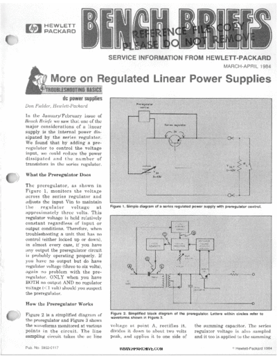
c What the Preregulator Does
The preregulator, as shown in
3-43v
Figure 1, monitors t h e voltage A
across t h e series regulator and
adjusts the input Vin to maintain
the regulator voltage at Figure 1. Simple diagram of a series regulated power supply with preregulator control.
approximately three volts. This
regulator voltage is held relatively
constant regardless of input o r
output conditions. Therefore, when
troubleshooting a unit that has no
control (either locked up or down),
in almost every case, if you have
any output the preregulator circuit
is probably operating properly. If
you have no output but do have
regulator voltage (three to six volts),
again no problem with the pre-
regulator. ONLY when you have
BOTH no output AND no regulator
voltage (<1volt) should you suspect
the preregulator.
How the Preregulator Works
Figure 2 is a simplified diagram of Figure 2. Simplified block diagram of the preregulator. Letters within circles refer to
f the preregulator and Figure 3 shows
waveforms shown in Figure 3.
the waveforms monitored at various voltage a t point A, rectifies i t , the summing capacitor. The series
points in t h e circuit. The line divides it down to about two volts regulator voltage is also sampled
sampling circuit takes the ac line peak, and applies it to one side of and it too is applied to the summing
Pub. NO. 5952-0117 WWW.HPARCHIVE.COM Hewlett-Packard 1984
capacitor. This causes a dc shift in
the B waveform as shown in Figure 3.
As the waveform goes in a pos-
itive direction through the firing
threshold (approximately -0.6V), the
pulse generator is "reset." When the
waveform goes negative through
this threshold, the pulse generator B
fires and produces a pulse that turns
on triac CR1. By increasing the dc FIRING THRESHOLD
level, when the regulator voltage is
high, the firing pulse is retarded;
decreasing the; dc level causes it to - I I I I
advance. Waveform E shows the I
I
I FIRE a
n
I
portion of the line voltage applied
n n
I I
to the main transformer as a result
I
D 1
I
of this controlled firing. Since the I
I I
I
I
I
circuit can only produce a pulse I
L
while C is going negative, the
earliest the triac can be turned on
is after the peak (90 degrees). Once
the triac has been fired, it continues EXRLY FIRING LATE FIRING
to conduct until the line crosses zero.
The variable ramp adjust provides Figure 3. Waveforms measured at the corresponding points shown in Figure 2.
you a means to adjust the series
regulator voltage (see the heading C high. If you remove the load from any stage is turned off, or a t the
"Regulator Voltage Control") and to the output and set the front panel other extreme, saturated, you are no
controls to mid-range, you can lift longer "in regulation" and t h e
compensate for component toler-
ances. (Note that in some supplies the components tied to C from each instrument will normally exhibit "7
t h e primary triac is replaced protection circuit. If the series one of three symptoms.
by two SCR's in the secondary.) regulator voltage comes up you are
on the right track. It will be locked up (high output)
This triac control technique is also It will be locked down (no output)
used in many units without series Regulator Voltage Control It will have high ripple
regulators, such as the HP 6400
series supplies. These range from Within the main loop of a series reg- In linear supplies with pre-
single-phase 200-watt to lOKw 3- ulated power supply (between the regulators, the voltage across the
phase supplies. In these supplies the voltage summing junction and the series regulators is at a low value
preregulator monitors the output series regulator), the transistors fairly close to its saturation voltage.
voltage and current and adjusts the controlling t h e output must be Figure 4 shows a n example
firing angle t o keep the output operated in their linear region. If of a normal waveform across the
constant.
Another important aspect of this
circuit is t h a t when you pull C
positive, no pulses are produced and
the input line is effectively turned
off. This feature is used to disable
t h e input under certain fault
conditions. One example is when the
crowbar fires. Not only is the output
shorted but the input is turned off
a t the same time.
Keep this feature in mind when
troubleshooting a supply with no L
r e g u l a t o r voltage. One of t h e Figure 4. Example of normal series regulator voltage waveform when the regulator is
protection circuits may be holding operated in its linear region.
2 BENCH BRIEFS MARCH-APRIL 1984 WWW.HPARCHIVE.COM
series regulator. To keep the series
regulator operating in its linear
' region, the regulator voltage is set
s o there is some "margin." This
margin ensures t h a t the "valley
voltage" never drops below the
saturation voltage "Vsat" of the
transistors. If the regulator voltage
goes low as shown in Figure 5, the
transistors saturate and clip the
bottom of the waveform. The clipped
portion then appears on the output
of the supply as high ripple at twice
the line frequency. Therefore, when
troubleshooting a unit with high
ripple, check the regulator voltage Figure 5. Series regL.Ator voltage is low which causes the transistors to saturate and
clip the bottom of the waveform. The clipped portion appears on the supply output as
with a dc coupled scope. ripple at twice the line fequency.
And remember, when making the -6.2 -6.2
preregulator tracking adjustment,
setting the regulator voltage too
high increases the power dissipated
in the series regulators and may
cause f a i l u r e s d u e t o h i g h
temperature. Setting the voltage
lower than specified will cause high +
ripple and loss of regulation.
U
C' short-circuit Protection
- y n
T-
-
Earlier i n this article we talked
about using the preregulator to
monitor the voltage across the series
regulator and adjust Vin t o Figure 6. Short-circuit protection preregulator circuit. This circuit limits the current
output to approximately 10 % of the supply's maximum rating.
maintain t h e regulator voltage.
Because the input circuit contains a -6.2
large capacitance there is a
significant delay in its response.
This delay can cause short-term
high power dissipation i n t h e
regulator. Figure 6 shows a circuit
that eliminates this problem.
Resistors R24 and R25 compare the
voltage across the regulator to the
-6.2 volt reference. When the reg-
ulator voltage exceeds a preset level
of about eight volts, Q20 turns on
and places R26 in parallel with the
current pot R123. This effectively
"turns down" the current limit to
about 10 percent of the supply's
f- maximum rating. The output
current is held at this level until
Figure 7. Short-circuit protection preregulator circuit. This circuit will reduce the supply's
output to zero.
the input capacitor bleeds down and If your supply will only output about A similar circuit is shown in Figure 7.
reduces the regulator voltage below 10 percent of its current, this is a In this circuit, when the regulator
eight volts again. good place to start troubleshooting. voltage goes high, Q802 turns on
WWW.HPARCHIVE.COM MARCH-APRIL 1984 BENCH BRIEFS 3
which turns the series regulator off
and reduces the output to zero.
L i f t i n g one e n d of R815 will Don Fielder is a product support
eliminate this circuit. engineer working for Hewlett-Packard
at t h e N e w J e r s e y D i v i s i o n in
Rockaway. He has been with HP for
Remember these are "protection" 23 years in a variety of positions
circuits and are supposed to activate including manufacturing, product
w h e n e v e r t h e series r e g u l a t o r assurance, and marketing.
voltage goes high; otherwise, they
are both off. I I
Safety-Related
Service Notes
Service Notes from HP relating to
personal safety and possible equip-
ment damage are of vital impor-
tance to our customers. To make
you more aware of these important
notes, they are printed on paper
with a red border, and the service
note number has a "-S" suffix. In 140AlBlS and 141AlBlS Note that this hazard does not exist
order to make you immediately Oscilloscopes on units with plastic or bakelite fan
aware of any potential safety prob- housings.
lems, we are highlighting safety- A shock hazard may exist on the
related service notes here with a HP 140's metal fan housing or any To reduce the possibility of a shock
brief description of each problem.
Also, in order to draw your atten-
metal part common to it. The metal
fan assembly is shock mounted and
hazard on instruments with a metal
fan housing, it is necessary to install
' 7
tion to safety-related service notes electrically isolated from ground. a ground wire from the fan housing
on the service note order form a t the Therefore, if any of the regulator to chassis ground. For details on this
back of Bench Briefs, each appro- transistors, thermal switch, or the procedure, please order safety
priate number is highlighted by fan motor itself shorts to the fan service notes 140AIBlS-16S o r
being printed in color. housing, a shock hazard could exist. 141AlBlS-21s.
Service Tips
Potential Handle Breakage
Don't Inadvertently Drop If you h a v e a n H P 180 s e r i e s
Your HP 180 Series instrument with a black polymer
Oscilloscope handle, periodically inspect the
handle to determine if it is becoming
Some handle breakage has been brittle or cracked. If it is, replace
reported on older cabinet versions of the handle with one of the following
H P 180 series oscilloscopes and new handles containing a metal
displays. The handles t h a t have band for increased strength and
broken were discontinued in 1979 reliability.
and are made of black polymer. They
would normally last the lifetime of 180NClF
the instrument; however, in some
higher temperature and humidity
181AIT
183AIC HP part no. 1440-0152
7
e n v i r o n m e n t s t h e h a n d l e may 184A The handles can be ordered for a
become brittle, crack and eventually nominal price from your local
fail. 182AIClT HP part no. 1440-0151 Hewlett-Packard Sales Office.
4 BENCH BRIEFS MARCH-APRIL 1984 WWW.HPARCHIVE.COM
Improve Your HP 410C HP 4955A Protocol Analyzer
Voltmeter Noise Rejection
This issue of Bench Briefs offers
There is a simple modification that eight service notes for improving
you can make to your HP 410C that the performance and reliability of
will improve the dc accuracy when the HP 4955A. There is a service
operating i n a n RF environment. note that outlines tape system
The modification consists of adding improvements, one to improve the
a 10K resistor in series with each performance a t turn-on, and a
gate of Q1 on the A3 photo-chopper service note describing a simple
board (0410-66502). procedure to improve battery life on
The parts required are: 9. Update the manual to reflect a few instruments. These particular
1 ea Test pin 0360-1716 these changes. units always need to have the real
2 ea 10K resistors 0757-0442 time clock and security restrictions
For more information order service reset whenever the instrument is
note 410C-24A. turned on.
Procedure
Attention HP 3776 A/B Please take a moment and order
1. Remove C13 and set it aside for Owners! these notes with the order form at
use in step 4. the rear of Bench Briefs.
2. Remove the jumper t h a t runs This issue of Bench Briefs contains
from cloverleaf #1 to cloverleaf several service notes that may be of
#2. interest to you. These notes contain
3. Add one of the 10K resistors HP 6453A, 6456B,
modifications that will improve the
between cloverleaf # 1 and #2. reliability and performance of the and 6459A SCR-Regulated
4. Connect the black end of C13 to H P 3776A/B PCM Terminal Test DC Power Supplies
finger # 4 and connect the other Set. There are two notes that detail
end of C13 to cloverleaf # l . modifications t o improve perfor- These power supplies contain
5. Lift the righthand gate of Q1 and mance when the TRANSIENTS germanium transistors that are no
solder a testpin in the hole. measurement is running, and a longer available for replacement.
6. Solder the gate lifted in step 5 to note that describes where all the Service notes 6453A-4, 6456B-4, and
the testpin just added. protective fuses are located. 6 4 5 9 A - 4 describe t h e silicon
7. Cut the trace that runs from Q1 replacements for these transistors in
testpin to finger #7. Owners of the HP 3776A/B can the event of their failure. Please
8. Connect the second 10K resistor order these service notes with the order these service notes with the
between Q1 testpin and finger # 7. order form located on the last page order form on the last page ofBench
of Bench Briefs. Briefs.
Use the order form at the rear of
Bench Briefs to order, free of charge,
individual Service Notes document-
l l ing several instruments.
If you would like to purchase large
quantities of Service Notes covering
a wide range of instruments, or if
you desire a complete history of all
Service Notes documenting a!l
Need Any Service Notes? changes to your instruments, Hew-
lett-Packard offers a microfiche li-
They're free! brary for a modest, one time charge.
There is also a microfiche subscrip-
Here's the latest listing of Service Notes. They recommend modifications to tion service available that automat-
Hewlett-Packard instruments to increase reliability, improve performance, ically updates the library on a
or extend their usefulness. quarterly schedule.
WWW.HPARCHIVE.COM MARCH-APRIL 1984 BENCH BRIEFS 5
I
I
The part numbers for the microfiche 3060A BOARD TEST SYSTEM 3771A/B DATA LINE ANALYZER
3060A-55. All serials. Using proper -hp- model 3253A 3771AiB-28. 3771 B serials below 222711-00173, 3771A
library and subscription service are: analog stimulusiresponse unit to measure operating serials below 233211-00450. Modification to prevent
amplifier (MOA) common mode rejection ratio possible interference at low levels when performing
Library of (CMRR) test. impulse noise measurements.
3776A/B PCM TERMINAL TEST SET
I
Service Notes- 5951-6511 3061A/3062A BOARD TEST SYSTEM
3061A-2. All serials. Software revisions for updating 3776A-1, Serials 233711-00122 and below. Modification
Subscription service- 595 1-6517 and minor enhancements. to prevent possible keyboard LED interaction when
3062A-2. All serials. Software revisions for updating a front panel key is depressed.
and minor enhancements. 3776A-2. Serials below 233011-00112 (option 001).
Contact your local HP Sales Office Modification to prevent possible residual phase jitter
for ordering information 3065 BOARD TEST SYSTEM problem with filter B (4Hz to 300Hz) selected.
3776A-3. Serials below 233OU-00112 (option 001).
3065-6. Serial numbers 2308A00101, 2308A00102,
Modification to prevent spurious interrupt occurring,
2308A00103, 2 3 0 8 A 0 0 1 0 4 , 2 3 0 8 A 0 0 1 0 5 ,
causing error 96 to be displayed.
140A/B/S and 141A/B/S 2308A00106, 2 3 0 8 A 0 0 1 0 7 , 2 3 0 8 A 0 0 1 0 8 ,
3776A-4. Serials below 233011-00112 (option 001).
OSCILLOSCOPES 2308A00110, 2 3 0 8 A 0 0 1 1 1 , 2 3 0 8 A 0 0 1 1 3 ,
Modification to improve performance when running 4
140AiBiS-16s. All serials. Modification to prevent a 2308A00114, 2 3 0 8 A 0 0 1 1 5 , 2 3 0 8 A 0 0 1 1 6 ,
TRANSIENTS measurement.
potential shock hazard. 2308A00117, 2308A00118, 2308A00119. RFI
3776A-5. Serials below 234011-00132. Modification to
141AIBIS-21S. All serials. Modification to prevent a modifications to 3 0 6 5 6 cabinet: installation
improve performance while in the IDLE STATE -
potential shock hazard. procedure and parts list.
PSOPH measurement.
3065-7. 3065C serials 2308A00155 and below.
3776A-6. Serials below 234011-001 32. Software
180 SERIES OSCILLOSCOPES/DISPLAYS Modification to allow remote 10 and memory
1
modification to prevent unstable signatures when
180AiF-13. All serials. Recommended new carrying reconfiguration.
troubleshooting assembly A9.
handle. 3776A-7. All serials. Where the protective fuses are
18OC-5. Serials 1935A and below. Recommended new 3468A DIGITAL MULTIMETER located.
carrying handle. 3468A-3. Serials 2137A03601 through 2137A05980. 3776A-8. Serials below 2347U-00152. Modification to
181A-11. Serials 2045A and below. Recommended Printed circuit board changes and signature analysis. orevent intermittent corruption of the non volatile
new carrying handle. memory (NVM).
181T-4. Serials 2034A and below. Recommended new 3478A DIGITAL MULTIMETER 37768-1. Serials below 233811-00142. Modification to
carrying handle. 3478A-4. All serials. Recommended replacement of prevent keyboard LED interaction when a front panel
182AiC-4. Serials 1941A and below. Recommended the outguard program ROM (U502). key is depressed.
new carrying handle. 37766-2. Serials below 233011-00112. Modification to
182T-2. Serials 1941A and below. Recommended new 3497A DATA ACQUISITION/CONTROL eliminate residual phase jitter problem with filter B
carrying handle. UNIT (4HZ to 300Hz) selected.
183AiC-10. All serials. Recommended new carrying 3497A-16. Recommended replacement to improve 37768-3. Serials below 233011-00112 (option 001).
handle. stability of voltmeter option current source. Modification to prevent spurious interrupt occurring,
184N-5. Serials 2017A and below. Recommended new 3497A-17. Recommended resistor replacement to causing error 96 to be displayed.
carrying handle. improve voltmeter option stability. 37768-4. Serials below 233011-00112 (option 101).
3497A-18. Recommended power supply replacement. Modification to improve performance when running
410C ELECTRONIC VOLTMETER
41 OC-24A. Serials 0982A22439 to 0982A23564.
Modification to improve noise rejection when
operating in an RF environment.
37028 lF/BB RECEIVER
3 7 0 2 8 - 4 9 . Serials 21 2 2 U - 0 3 4 5 1 a n d below.
Modification to reduce spurious signals.
TRANSIENTS measurement.
37768.5. Serials below 234011-00152. Modifications
to improve performance while in the IDLE STATE
- CMESS measurement.
37768-6. Serials below 234011-001 52. Software
r-
419A DC NULL VOLTMETER modification to prevent unstable signatures when
3712A IF/BB RECEIVER troubleshooting assembly A9.
41 SA-7B-S. Serials 0948A05467 and below.
Modification to eliminate potential shock hazard. 3712A-11. All serials. Changes to Y deflection 37768-8. Serials below 2346U-00182. Modification to
sensitivity and normalizer programs. prevent intermittent corruption of the non volatile
memory (NVM).
853A SPECTRUM ANALYZER DISPLAY
3730B DOWN CONVERTER
853A-2. Serial 2223A. Recommended high-voltage 3777A CHANNEL SELECTOR
3730B-3. All serials. Instrument and manual part
transformer replacement kit. 3777A-1B. Serials 230911-00745 and below. Preferred
number changes.
853A-8. All serials. Preferred replacements for replacement of relays.
capacitors A5C5, C14. C28, C36, C37, and C47.
853A-9. Serials 2223A00265 and below. Replacing 3746A SELECTIVE LEVEL MEASURING 3779A/B PRIMARY MULTIPLEX
broken handle hub gears and handle pivots. SET ANALYZER
3746A-9A. All serials. Preferred replacement for CR3. 3779A-29. All serials. Improved specification for service
1345A X-Y DISPLAY 3746A-11. All serials. Where the protective fuses are accessories (SAI, SA2, SA3, SA4).
1345A-18. Serials 2112A00475 and below. How to fix located. 3779A-30. All serials. Modification to improve out-of-
loose PA. leads. 3746A-12. Serials 23201100372 and below. Preferred band noise immunity.
replacement for resistor A1 R32. 37798-31. All serials. ModLfication to improve out-of-
1345A DIGITAL DISPLAY MODULE band noise immunity.
1345A-2. Serials 2227A and below. Installation note 3762A DATA GENERATOR
3762A-6. All serials. Where the protective fuses are
3779C/D PRIMARY MULTlPLEX
for test pattern update kit, PIN 01345-69505. ANALYZER
located.
3762A-7. All serials. Prevention of subsequent power 3779C-1-A. All serials. Modification to improve
1950A TWO CHANNEL EXPANSION compatibility between 3779C & 3779A for single
supply failure.
MODUE channel looping.
1950A-1. Serials 2323A and below. Modification to 3779C-38. Serials 221511 and below. Modification to
correct improper EO1 assertion over HP-IB. 3763A ERROR DETECTOR protect relays at switch-on.
3763A-8. All serials. Where the protective fuses are 37790-9. Serials 22351100289 and below. Preferred
located. replacement for EPROMS 1135, 1136, and U66 on
1965A GATED UNIVERSAL COUNTER
3763A-9. All serials. Prevention of subsequent power A13 board.
EXPANSION MODULE supply failure.
1965A-2. Serial 2310A. Modification to correct improper 3779C-13. All serial numbers (option 003). Conversion
3763A-10. All serials. Modification to improve return of digital clock to 75ohms unbalanced output.
EO1 assertion over HP-IB. loss on CMI input. 3779C-15. Serial numbers below 23081100309.
Modificationto improve out-of-band noise immunity.
1980A/B OSCILLOSCOPE MEASUREMENT 3764A DIGITAL TRANSMISSION 3779D-l A. All serials. Modification to improve
SYSTEM
198ONB-5C. Serials 2131A- and below. Recommended
HP-18 talkilisten and ROM replacement.
1980NB-108. 1980A serials 2240A- and below; 198OB
ANALYZER
3764A-1. All serials. Where the protective fuses are
located.
compatibility between 3779D & 37798 for single
channel looping.
3779D-38. Serials 221311 and below. Modification to
protect relays at switch-on.
e
serials 2216A- and below. Modification to prevent 3770A/B TELEPHONE LINE ANALYZER 3779D-9. Serials 22351100224 and below. Preferred
random bus lock up or syntax errors. 3770A-43. All serials. Preferred replacement of 16 pin reolacement for EPROMS U35, 1136, and U66 on
1980AiB-17. 1980A all serials; 1980B serials 2142A IC socket HP part number 1200-0767. A13 board.
- through 2338A. Modification to correct improper 37706-27. All serials. Preferred replacement of 16 pin 3779D-16. Serials below 23081100244. Modification to
EO1 asssertion over HP-IB. IC socket HP part number 1200-0767. improve out-of-band noise immunity.
6 BENCH BRIEFS MARCH-APRIL 1984 WWW.HPARCHIVE.COM
3780A PATTERN GENERATOWERROR 6453A DC POWER SUPPLY 8565A SPECTRUM ANALYZER
DETECTOR 6 4 5 3 A - 4 S e r i a l s 2233A a n d below. S i l i c o n 8565A-168. All serials. Log amplifier adjustment
3780A-27A. All serials. Retrofit of option 101. replacements for germanium transistors.
7 3780A-28. All serials. Modification to prevent power
supply failure. 64568 DC POWER SUPPLY
6 4 5 6 8 - 4 . S e r i a l s 2236A a n d below. S i l i c o n
8640NB SIGNAL GENERATOR
8640A-30. Serials 2222A and below and all U prefixes.
FM amplifier reliability improvement.
3781 B ERROR DETECTOR replacements for germanium transistors. 86408-35. Serials 2229A and below and all U and G
37818-6. All serials. Where the protective fuses are prefixes. FM amplifier reliability improvement.
located. 6459A DC POWER SUPPLY
6 4 5 9 A - 4 . S e r i a l s 2235A a n d below. S i l i c o n 8656A SIGNAL GENERATOR
3782A/B ERROR DETECTOR replacements for germanium transistors. 8656A-16. Serials 21 11A and below. Recommended
3782A-3. All serials. Where the protective fuses are output assembly replacement.
located. 6942A MULTIPROGRAMMER
3782A-4. All serials. Modification to prevent power 6942A-7A. 14711A. Field service kit for the 6942A 8662A SYNTHESIZED SIGNAL
supply failure. Multiprogrammer. G ENERAT0R
37828-6. Serials 231OW00396 and below. Preferred 8662A-9. Serials prefix 2340A and below. Modification
replacement of reference sequence generator A35 8011A PULSE GENERATOR to prevent line fuse blowing during 230 VAC
assembly. operation.
801 1 A-7. Serials 21 11A and below. Preferred
37828-7. All serials. Where the protective fuses are
replacement for resistor A1 R45.
located. 8663A SYNTHESIZED SIGNAL
MODEL 8165A PROGRAMMABLE SIGNAL GENERATOR
3785NB JITTER GENERATOR & 8663A-2. Serials prefix 2339A and below. Modification
RECEIVER GENERATOR
to prevent line fuse blowing during 230 VAC
3785A-9. All serials. Preferred replacement for A35U2. 8165A-10. Serials 2248G02140 and below. Modification
operation.
37858-8. All serials. Preferred replacement for A35U2. of -29V voltage source on A5 timing board.
8672A SYNTHESIZED SIGNAL
3964N3968A INSTRUMENTATION TAPE 8406A COMB GENERATOR GENERATOR
RECORDER 8406A-3. Serials 2246A02245 and below. Power supply 8672A-15. All serials. Retrofit kit to modify 8672A for
3964A-20A. All serials. FM data PCA PIN 03964-60506 modifications - fuseholder and A I V R l .
compatibility with 86720A. Supercedes 8672A-11
or 03964-60508 calibration instructions. and 8672A- 13.
3968A-22. All serials. FM data PCA PIN 03964-60506 85548 SPECTRUM ANALYZER RF
or 03964-60508 calibration instructions. SECTIONS 11253NB POWER MODULE ALL -
85548-38. Serials 2011A and below. RF input OPTIONS
4910G FAULT LOCATOR attenuator replacement kit. 11253A-1. All serials. Alternate procedure for adjusting
491 OG-4. Serials 1636A00525 and below. 12-volt 85548-5A. All serials. Modification to install option 003, and performance testing the HiILo line trip points.
battery modification. internal RF input limiter. 112538-1. All serials. Alternate procedure for adjusting
85548-8A. Serials 21 11A and below. Precaution on and performance testing the HiiLo line trip points.
4930A FAULT LOCATOR changing A7 YIG oscillator assembly.
4930A-6. Serials 1522A01415 and below. 12-volt 85548-9. Serials 21 11A and below. Preferred 37201A HP-IB EXTENDER
battery modification. replacement of attenuator ATl. 37201A-4. Serials 223211 and above. Retrofit procedure
85548-10. Serials 21 11A and below. Preferred for OPT 050 remote HP-I8 interface.
4936A TlMS replacement of attenuator A7AT1,
4936A-1. Serials 2141A. 221 1A and 21 1OU. Preferred 44538N44539A/44540A TEST FIXTURE
replacement for A4 transmitter board. 8554L SPECTRUM ANALYZER KIT .
4936A-2. All serials. Retrofit for battery operation 8554L-9. All serials. Preferred replacement of 44538AI44539A144540A-1. Serial numbers: not
(options 001 and 003). attenuator AT1. applicable. Improving patch panel plug to paddle
8554L-10. All serials. Preferred replacement of pin connections.
4955A PROTOCOL ANALYZER attenuator A7ATl.
4955A-28. Serials 2248A and below. Tape system 8554L-11. All serials. Preferred RF input attenuator 64000 LOGIC DEVELOPMENT SYSTEM
improvements. replacement kit. Supercedes 85548-3A. 64000-OF: Service note index.
4955A-3. Serials 2309A and below. Modification to
prevent excessive HP-I8 loading. 8555A SPECTRUM ANALYZER 64110A LOGIC DEVELOPMENT
4955A-4. Serials 2317A and below. Modification to 8555A-2A. All serials. Precautions on replacing input MAINFRAME
improve performance at turn-on. mixer assembly. 641 10A-7. Serials 2326A and 2328A. Modification
4955A-5. Serials 2309A and below. Modification to 8555A-68. Serials 2209A and below. Precaution on before using the SA loop K in troubleshooting.
prevent premature battery failure. changing YIG oscillator assembly A3.
4955A-6. Serials 2320A. Interface interconnect cable 8555A-20. Serials 2209A and below. Preferred
miswires.
64242A 68000 EMULATOR SUBSYSTEM
replacement of attenuator A3ATl. 64242A-5A. Serials 2124A and below. 68000 emulator
4955A-7A. Serials 2320A and below. Modification to
prevent display failures and LP interface - dynamic enhancement for 10 MHz operation.
RAM failures. 8556A SPECTRUM ANALYZER
4955A-8. Serials 2331A and below. Modification to 8556A-4. Serials 2148A05265 and below. Power supply 64250A 280 EMULATOR SUBSYSTEM
correct high voltage failures. modifications - AlOQ1, A10Q2, and AlORl 64252A-lA3. 280 emulator pod board repair number
8 5 5 6 A - 5 . S e r i a l s 2 1 4 8 A 0 5 2 8 5 a n d below. 2003A-00126 and above. User NOT WAIT signal
4961A PAIR IDENTIFIER Recommended A8 germanium diode replacement. treatment for execution from emulation memory.
4961A-6. Serials 1706A00175 and below. 12-volt
battery modification. 8557A SPECTRUM ANALYZER 64601A TIMING ANALYZER CONTROL
8557A-11. Serials 2203A and above. Procedure for BOARD
5180A WAVEFORM RECORDER selecting resistor A1A1 R2 64601A-2. All serials. Jumper necessary for signature
5180A-128. Serials 2204A00191 and below. Change analysis tables 3 through 8.
to the bottom cover and information pull-out cards. 8559A SPECTRUM ANALYZER
8559A-23. Serials 2320A02910 and below. Modification 86632B MODULATION SECTION
5328A UNIVERSAL COUNTER to prevent high frequency lockup of A5A1. 866328-1. Serials 2251A02245 and below. A3 remote
5328A-37A. All serials. (Std. counter only). Modification 8559A-24. All serials. Replacing resistors in -12V attenuator assembly replacement.
to correct intermittent miscounting. regulator of frequency control assembly A7.
5328A-38. Serials 2304A and below (std. and H99 8 5 5 9 A - 2 5 . S e r i a l s 2 2 4 0 A 0 2 3 1 1 a n d above. 86635A MODULATION SECTION
counters). Modification to Drevent intermittent aate Modifications to improve performance using the 86635A-1. Serials 2306A00840 and below. A3 remote
light indication. mixer cable assembly. attenuator assembly replacement,
3
WWW.HPARCHIVE.COM MARCH-APRIL 1984 BENCH BRIEFS 7
Service 1 rder Form
If you want service notes, please For European customers (ONLY) Name
check the appropriate boxes below
and return this form separately to Hewlett-Packard Firm
one of the following addresses. Central Mailing Dept. Address
P. 0. Box 529
Hewlett-Packard Van Hueven Goedhartlaan 121 City
1820 Embarcadero Road AMSTELVEEN-1134
State Zip
Palo Alto, California 94303 Netherlands
0 140NVS-16S 0 3065-6 0 3776A-4 0 3780A-27A 0 5328A-38 0 8565A-168
0 141NWS-21S 0 3065-7 0 3776A-5 0 3780A-28 0 6453A-4 0 864OA-30
0 18ONF-13 0 3468A-3 0 3776A-6 0 37818-6 0 64568-4 0 86408-35
0 18OC-5 0 3478A-4 0 3776A-7 0 3782A-3 0 6459A-4 0 8656A-16
0 181A-11 0 3497A-16 0 3776A-8 0 3782A-4 0 6942A-7A 0 8662A-9
0 181T-4 0 3497A-17 0 3776B-1 0 37828-6 0 8011A-7 0 8663A-2
0 182NC-4 0 3497A-18 0 37768-2 0 37828-7 0 8165A-10 0 8672A-15
0 182T-2 0 37028-49 0 37768-3 0 3785A-9 0 8406A-3 0 11253A-1
0 183NC-10 0 3712A-11 0 37768-4 0 37858-8 0 85548-38 0 112538-1
0 184A-5 0 37308-3 0 37768-5 0 3964A-20A 0 85548-5A 0 37201A-4
0 410G24A 0 3746A-9A 0 37768-6 0 3968A-22 0 8554B-8A 0 44538N
0 419A-78-S 0 3746A-11 0 37768-8 0 491OG-4 0 85548-9 44539N
0 853A-2 0 3746A-12 0 3777A-1B 0 4930A-6 0 8554B-10 44540A-1
0 853A-8 0 3762A-6 0 3779A-29 0 4936A-1 0 8554L-9 0 64000-OF
0 853A-9 0 3762A-7 0 3779A-30 0 4936A-2 0 8554L-10 0 64110A-7
0 64242A-5A
0 1345A-1B 0 3763A-8 0 37798-31 0 4955A-28 0 8554L-11
0 1345A-2 0 3763A-9 0 3779C-1A 0 4955A-3 0 8555A-2A 0 64252A-1A3
0 1950A-1 0 3763A-10 0 3779C-38 0 4955A-4 0 8555A-68 0 64601A-2
0 1965A-2 0 3764A-1 0 3779c-9 0 4955A-5 0 8555A-20 0 866328-1
0 198ONB-5C 0 3770A-43 0 3779C-13 0 4955A-6 0 8556A-4 0 86635A-1
0 1980NB-10B 0 37708-27 0 3779C-15 0 4955A-7A 0 8556A-5
0 198ONB-17 0 3771NB-28 0 3779D-1A 0 4955A-8 0 8557A-11
0 306OA-55 0 3776A-1 0 3779D-38 0 4961A-6 0 8559A-23
0 3061A-2 0 3776A-2 0 3779D-9 0 5180A-12B 0 8559A-24
0 3062A-2 0 3776A-3 0 3779D-16 0 5328A-37A 0 8559A-25
Please photocopy this order form if you do not
want to cut off the page
HEWLElT-PACKARD COMPANY Bulk Rate
1820 Embarcadero Road
Palo Alto California 94303 U S Postage
BENCH BRIEFS Sunnyvale, CA
MARCH-APRIL 1984 Permit No
Volume 24 Number 2
Service information from
Hewlett-Packard Company
To obtain a qualification form for a free
subscription, send your request to the
above address.
Reader comments or technical article
contributions are welcomed.
Please send them t o the
Bench Briefs Editor.
Editor: Jim Bechtold
r
Hewlett-Packard
690 E. Middlefield Rd.
Mt. View, CA 94042
All rights reserved Permission to reprinl Bench Brlefs granted upon written request to the Editor Printed in U.S.A.
8 BENCH BRIEFS MARCH-APRIL 1984 WWW.HPARCHIVE.COM
◦ Jabse Service Manual Search 2024 ◦ Jabse Pravopis ◦ onTap.bg ◦ Other service manual resources online : Fixya ◦ eServiceinfo