Service Manuals, User Guides, Schematic Diagrams or docs for : HP Publikacje HP-Bench-Briefs-1986-07-10
<< Back | HomeMost service manuals and schematics are PDF files, so You will need Adobre Acrobat Reader to view : Acrobat Download Some of the files are DjVu format. Readers and resources available here : DjVu Resources
For the compressed files, most common are zip and rar. Please, extract files with Your favorite compression software ( WinZip, WinRAR ... ) before viewing. If a document has multiple parts, You should download all, before extracting.
Good luck. Repair on Your own risk. Make sure You know what You are doing.
Image preview - the first page of the document
>> Download HP-Bench-Briefs-1986-07-10 documenatation <<
Text preview - extract from the document
HEWLETT
PACKARD
Barry Halm,
HP New Jersey Division
Flyback Converters -
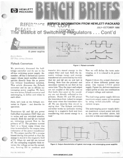
Figure 1. Flyback converter
We previously discussed the half-
bridge converter and its use in the transfer this stored energy to the Now we will define the term auto-
off-line switching power supply. Re- output filter and load. Both the dy- ranging, as it is related to dc power
member, off-line is defined as a power namic voltage range and energy supplies.
supply whose input rectifier circuits transferred are controlled by the time
operate directly from the ac power that Q1 and Q2 are on and Ipri is Figure 2 shows the output character-
line without transformer isolation. flowing. Note that the primary and istics of three different power sup-
This article discusses the flyback secondary current do not flow at the plies. The typical CV/CC power
converter and its use in off-line au- same time. Thus the input and output supply, Figure 2A, delivers maximum
toranging power supplies. We have are not coupled at the same time so output power at only one combination
two new terms, flyback converter and that faults that occur on the second- of output voltage and current.
autoranging, to define and relate to ary are not directly reflected to the
each other. primary. Diodes D1 and D2 protect The dual-range power supply delivers
the transistors from inductive surges maximum output power at two points
First, let's look at the flyback con- that occur when the transistors turn by using switch-selectable voltage/
verter in Figure 1 and describe its off. We can describe this circuit by current ranges.
operation. saying that "The flyback switching
converter works by cyclically storing The autoranging power supply deliv-
Transistors Q1 and Q2 are power energy in a magnetic field and then ers maximum output power not only
field-effect transistors (FET) that are transferring this stored energy to a at the points described above, but
in series and are switched simulta- load." also over a wide and continuous range
neously. Both Q1 and Q2 are turned
on, initiating current flow in the
primary of T1. The primary current MAX
(Ipri) is a linear ramp whose rise
time is controlled by the magnetizing
inductance of the power transformer
T1. The output rectifier D3 is reverse
biased during this period so that the
energy is stored in the magnetic field 1
of T1. When Q1 and Q2 are turned
off, the collapsing magnetic field re-
Figure 2. Output characteristics of typical, dual-range, and autoranging power supplies
verses the voltage across the second-
ary, forcing D3 to conduct and
1\
Pub. NO.5952-0126 @ Hewlett-Packard 1986
WWW.HPARCHIVE.COM
of voltage and current combinations
as shown in Figure 2C. This auto-
ranging capability is made possible
WAVEFORM ACROSS R I
by the flyback converter's ability to
provide a greater variation of output
voltage with respect to changing duty
cycle.
Drive Circuits
ibl 0V
I-LT~
WAVEFORM Vbe
Figure 3. Simple bipolar base drive circuit
The two types of power transistors c
commonly used in switching regulator
circuits are bipolar and field-effect.
0 v r p J
While bipolar transistors are less (0'
i NEGATIVE
CURRENT
SPIKE
expensive, field-effect transistors re- W4VEFORM &ROSS RI
quire a simpler and less power-
consuming drive circuit. The bipolar
transistor, being a current-dependent
device, requires relatively large base
W4VEFORM Vbe
currents to obtain the necessary col- CR3
lector current.
Figure 4. Simple bipolar base drive circuit with turn-off
Bipolar-Figures 3 and 4 represent
simplified base drive circuits used in tgh the emitter-base junction used in FET switching. A p sitive
switching power supplies. of Q1 in the reverse direction. The ON pulse is applied to the gate of Q1 .
reverse current appears as the nega- through steering diode CR1. Although
Looking at Figure 3 and waveforms tive spike seen in the voltage wave- the ON pulse is of short duration, 1
3a. and 3b., we can see that when form across R1. to 2 microseconds, the input capaci-
the base of Q1 is positive with respect tance of the gate-source junction
to its emitter, the transistor conducts. The drive circuit of Figure 4 greatly
reduces the turn-off time of the power
maintains the gate voltage. Q2 is off
and CR1 is reverse biased, preventing
7
When the drive waveform from pulse
transformer T1 reverses, the base- switches. Because most of the power the gate from discharging. To turn
emitter voltage of Q1 collector current is dissipated during turn-on and turn- Q1 off, the gate voltage must be
continues to flow for a short period of off, the reliability of the power tran- reduced below a specific threshold
time. This time is called storage time sistors is increased. level or to zero.
and is defined as the interval of time
from the moment reverse base drive Field-Effect-The FET is a voltage- The OFF pulse from T2 will turn on
is applied to when the collector- controlled device. A voltage applied Q2, pull the gate voltage to zero, and
emitter voltage has reached 10 per- between the gate and source produces return the drain to a high impedance.
cent of its off value. To decrease a drain current. The gate is electri-
storage time, diodes CR1 and CR2 cally isolated from the source so only A more detailed description of power
are added to the drive circuit. CR1 a small leakage current will flow FET circuits is described in operating
prevents the collector from going from the gate when a signal is and service manuals for Hewlett-
more negative than the base, or into applied. Packard power supplies, such as the
"deep" saturation. HP 6033A. Also, see the August 1981,
Figure 5 is a typical drive circuit Hewlett-Packard Journal. 0
A second method of decreasing stor-
age time and thereby speeding up
turn-off is shown in Figure 4.When
the top of T1 goes positive, CR2 will
be forward biased, Q2 will be turned
off, and C1 will be charged up through
CR3. The drive signal is then removed
from the primary of T1 so the wave-
form will collapse and reverse the
voltage across the secondary. This
1
reverse voltage biases CR2 off, which
causes Q2 to turn on and discharge
Figure 5. Simplified FET gate drive
2 BENCH BRIEFS JULY-OCTOBER 1986
WWW.HPARCHIVE.COM
~~ ~~ -
New Adjustment Procedure Improves QTS-70 Service
MP 86&rr:A/B/DReliability Paining at Lexico
r Eric Jennings, i n Hewlett-Packard service notes Lexico E n t e r p r i s e s , K i r k l a n d ,
Washington, is currently offering a
HP Stanford Park Division 8684A-4, 8684B-4 and 8684D-1.
These notes are available from your 5-day class t h a t deals with t h e
There is a new procedure for adjusting nearest HP office or from the Lit- technical aspects of the HP DTS-70
the sloping power supplies in H P Circuit Test System.
erature Distribution Center at
8684A/B/D cavity-tuned Signa1 Gen- 1820 Embarcadero Road, Palo Alto,
erators that reduces the voltage to This course provides background in-
California, 94303.
the low oscillator circuits while using formation for the HP 1000 series
the high oscillator. This reduced volt- The procedure applies to all serial minicomputer, the TESTAID III/
age decreases heat dissipation and numbers and will be included in the FASTRACE I11 software and, in par-
improves oscillator life. yellow change sheet that accompanies ticular, the HP 9571 Digital Test
the instrument's operating and serv- Station. "he students learn to perform
For current owners of the signal ice manual for all new 8684s. o
generators the procedure is detailed and evaluate the system's functional
tests, performance tests, and to install
the test station hardware. Students
are also given the opportunity to
troubleshoot inserted faults on both
the instruments and t h e circuit
boards of the digital test unit.
The cost of this 5-day course is $1,450
per-person, per-session. For additional
information in the DTS-70 service
course and its 1986/87 training sched-
ule, please contact the registrar's
office at Lexico, (206) 828-0555. 0
The Bootstrap Figure 1 shows a standard junction
FET amplifier stage. In most appli-
The bootstrap principle allows the
use of a low value for R1 and still
Circuit cations, the input resistor R1 will keeps the high input impedance of
display a lower resistance than the the FET. Figure 2 shows the principle.
The bootstrap circuit is a circuit in input impedance of the FET and, in The output of the FET amplifier is
which an increment of the applied a way, destroys one advantage of a returned to the bottom of the input
signal is partially fed back across the FET amplifier, which is its high resistor R1 with same phase and
input impedance resulting in a higher input impedance. There are reasons same amplitude as the input signal.
effective input impedance. why R1 cannot be selected with a When the input signal is applied to
resistance as high or higher than the the FET, both ends of R1 are at the
In the "tube days" a bootstrap cir- FET input impedance, such as ther- same potential at all times, point A
cuit was a single-stage electron-tube mal noise, stability, etc. and B swing exactly in synchronism.
amplifier circuit in which the output
load was connected between cathode
and ground or other common return. +
The signal voltage was applied be-
tween the grid and the cathode. The
I name bootstrap came from the fact
that a change in grid voltage changed
the potential of the input source with
respect to ground by an amount equal
to the output signal.
In today's circuits, as then, one of the
(`- uses of the bootstrap circuit is to
L
overcome the shunting effect of the Figure 2. The same FET amplifier as in
Figure 1. Standard junction FET amplifier
input resistance of many kinds of stage Figure 1 but with positive feedback to the
electronic circuits. input that keeps the input impedance high
I JULY-OCTOBER 1986 BENCH BRIEFS 3
WWW.HPARCHIVE.COM
Therefore, no c u r r e n t can flow the effect of R1 will only be partially larger in resistance than the actual
through R1, and it becomes virtually eliminated, which for certain appli- resistive value.
an infinite resistance representing no cations may be sufficient. For exam-
load for the FET input. ple, if the FET is used as a source
follower for the bootstrap, the feed-
Figure 4 shows a typical bootstrap
circuit that is used in the HP 400E
/1
Since the signal fed back to point B back amplifier can be eliminated. Voltmeter. The input resistor R19 as
is in phase with point A, the feedback Figure 3 illustrates this solution. At well as the load resistor R23 are
is positive and the bootstrap circuit the input, R1 appears 20 to 50 times bootstrapped. 0
has a gain of exactly one. If the gain
were above one, the circuit would
oscillate. If it were lower than one,
Figure 3. FET used as source follower for Figure 4. Typical bootstrap circuit example from HP 400E Voltmeter
the bootstrap
Taking the Mystery Out of Probe Selection
Ed Mierzejewski, probes with some key specifications ohm inputs without selectable high
HP Colorado Springs Division that will help to determine which impedance inputs. This 10 Megohm,
probe makes the most sense for a 10 picofarad probe allows direct
Hewlett-Packard has been receiving given application. measurements of 100 volts (dc to
requests for probe information, some- 100 MHz) in the 1OO:l division ratio
thing to supplement the information If you need a n active probe we mode. In the 1O:l division ratio mode,
in the 1986 instrument catalog. recommend the HP 1124A 100 MHz the input voltage range is ? 10 volts.
Active Divider Probe that provides Power is supplied by instruments
Table 1 lists H P s current miniature high-voltage, general-purpose prob- with probe power jacks or the HP
and standard-size resistive divider ing capabilities for scopes having 50- 1122A Probe Power Supply. 0
Table 1. Resistive Divider Probes
HP Model Div. Ratio Resistance Shunt Cap. Compensates to Band Width Max. Voltage Size Length
10002A so:1 9Mn 2.5pF 15-55pF 40 MHz loo0V Standard ISM (4.9 ft)
10004D 10:I IOMn lOpF 20-30pF 100 MHz 500v Standard I.1M (3.6ft)
10005D 10:1 lOMn 17pF 20-30pF 100 MHz 500v Standard 3M (9.8 f t )
10006D IO: 1 IOMR 14pF 20-30pF 100 MHz 500v Standard 1.8M (5.9 f t )
10013A 1O:l lOMn 13pF 24-45pF 15 MHz 500v Standard 1.8M (5.9 ft)
10014A 10:1 IOMR lOpF 9-13pF 300 MHz 500v Standard 1.1M (3.6ft)
100168 1O:l IOMn 14pF 9-13pF 300 MHz 500v Standard 1.8M (5.9 f t )
10017A 10:1 1 MR 8PF 9-14pF 300 MHz 300V Mini 1M (3.3f t )
10018A 1O:l 1MR IOpF 9-14pF 200 MHz 300V Mini 2M (6.6 f t )
l002lA 1:1 36pF I O MHz 300V Mini IM (3.3f t )
10022A 1:l 62pF IO MHz 3oOV Mini 2M (6.6 f t )
10026A 1:l son l00V Mini 1M (3.3f t )
10027A 1:l son I oov Mini 2M (6.6 f t l
10032A 100:1 3Mn 3PF 9-14pF 300 MHz 300V Mini 1.1M (3.6f t l
1 W A 10: 1 1 MR YPF 20-.NpF 100 MHz 300v Mini I M 13.3 f t l
10041A 1O:l 1MR 12pF 20-3OpF 100 MHz 3ooV Mini 2M (6.6 f t )
10042A IO: 1 1Mn 15pF 20-3OpF 100 MHz 3oOV Mini 3M (9.8 f t )
10081A IO: 1 1 MR 12pF 12-20pF 100 MHz 300V Mini 2M (6.6 f t )
10084A 1:l 6RpF 100 MHz 300V Mini 2M (6.6 f t )
4 BENCH BRIEFS JULY-OCTOBER 1986
WWW.HPARCHIVE.COM
Recommended Reading
a quality-control loop is established connectors: to know what to look for
around both the equipment and the when cleaning and inspecting them,
measuring procedures. The SRMs are in order to preserve their precision
described in NBS Standard Reference and extend their life; and to make
Materials Catalog 1986-88, edited by the best possible microwave connec-
R. W. Seward, and in the supplemen- tions, improving the accuracy and
tary NBS Standard Materials Price repeatability of all of your measure-
List. ments, saving both time and money.
A complementary copy of those pub- To order the free Application Note
lications or information about the 326 (publication number 5954-1566),
services can be obtained from: contact the HP literature distribution
center at the address on the rear
Ernest L. Garner, Chief page of this issue of Bench Briefs.
Office of Physical Measurement
Services
National Bureau of Standards
B362 Physics Building
Calibration Services at the Gaithersburg, MD 20899
U.S. National Bureau U.S.A.
of Standards
Telephone: (301) 921-2805
Editor`s Note: In the interest of pro- Telex: TRT 197674NBS UT
viding a wider audience for infor-
mation on their technical services,
the US.Dept. of Commerce asked
c for a short presentation in various
company publications. Hewlett-
Packard is happy to provide this
information to our readers because
the NBS measurement services and Fiber Optics Handbook
standard reference materials provide
the technical references for a wide A n Introduction and Reference Guide
range of measurements world-wide. to Fiber Optic Technology and
Q
Measurement Techniques
Over 300 different calibration and
test services are described in the This handbook provides basic infor-
recently published NBS Calibration mation about fiber optic systems and
Services Users Guide 1986-88, edited Coaxial Systems components, and methods for evalu-
by G. A. Uriano, and in the supple- ating their performance. Fibers offer
mentary NBS Calibration Services Principles of Microwave Connector clear advantages over conventional
Fee Schedule. Services range from Care (For Higher Reliability and transmission media. These include
dimensional, to ionizing radiation, to Better Measurements) lower attenuation, larger bandwidth
highly-specialized microwave and freedom from electromagnetic
~ parameters. Recent advances in measurement ca- interference. Despite these advan-
pabilities have made RF connectors tages, the underlying basics and the
In addition to measurement services, and connection techniques more im- techniques involved in fiber optics
NBS provides another highly-inno- portant than ever before. Damage to are more complicated than, for ex-
vative program that supplies a meas- the connectors on calibration and ample, coaxial cables. This book is
urement reference path for quality verification devices, and on test ports, intended to help answer many ques-
control of measurements. NBS can cables, and other devices also repre- tions in a comprehensive and easy-
supply over 1000 different standard sents an increasing burden in down- to-read way.
reference materials (SRMs) for use time and expense.
f-. in manufacturing, materials testing, To order the Fiber Optics Handbook,
environmental measurements, and The suggestions in Application Note contact your nearest HP office and
clinical testing. By measuring such 326 will help you get the best per- order HP PIN 5952-9554. There is a
samples in the actual local situation, formance from all coaxial microwave charge for this book.
~ JULY-OCTOBER 1986 BENCH BRIEFS 5
WWW.HPARCHIVE.COM
Many Hewlett-Packard instruments instrument and programs that are ply that the software will run on all
and instrument-based systems use almost complete application tools. of the workstations. ?
ready-made programs, stored in both Some programs are not stored on a
tape and disc format, that will test, disc or tape but are printed in the In some instances, the software is
verify and exercise the instrument operating and service manual and part of a maintenance kit and cannot
or system in a variety of ways; all of need to be manually entered into the be purchased separately.
which are designed to provide the controller line-by-line.
user with a high confidence level that Please note that we have made every
the instrument/system is performing attempt to make sure this list is
the way it should. In some cases the controller is listed complete and accurate. However,
as HP Series 200. This means that since this list was compiled by hu-
Most of the programs are HP-IB the software may run on one or more man hand there will no doubt be
based and test the interface capa- of the following technical worksta- human errors. We have done our
bility of the instrument through a tions; Models 216,217,220,226,236, best. If you have any questions about
particular controller. There are pro- and 237 (ordered as 9816,9817,9920, this list, please contact your local
grams used for troubleshooting the 9826, 9836, 9837). This does not im- HP office.
HP ModelDescription TapeIDisc PIN Format Controller Documentation
10871A Service K i t 05180-13301 9825A 5180A Manual
11664E Detector i n manual S e r . 200 11664E Manual
11740A M Phase N o i s e Meas. Sys.
U 03047- 10015 5 1/4" d i s c 9836~ 3047A Manual
11740A MU Phase N o i s e Meas. Sys. 35601-10011 5 1/4" d i s c 9836~ 35601A Manual
1630/31 Logic Analyzer 01630-6a705 test k i t S e r . 200 1630/31 Manual
1630/31 Logic Analyzer 01630-90049 5 1/4" d i s c #1 S e r . 200 01630-68705 P r o d . Supt. Pkg.
1630/31 Logic Analyzer 01630-90050 5 1/4" d i s c #2 S e r . 200 01630-68705 P r o d . supt. Pkg
1630/31 E T 19776 01630-90051 5 1/4" d i s c S e r . 200 01630-68705 P r o d . S u p t . Pkg.
1630/31 66505 S t a t e B o a r d 01630-90039 5 1/4" d i s c S e r . 200 1630/31 Manual
1630/31 66509 S t a t e B o a r d 01630-90040 5 1/4" d i s c Ser. 200 1630/31 Manual
1630/31
1630/31
1630/31
66506 T i m i n g M s t r . B o a r d
66510-66524 Tmg.Mstr.Bds.
66508 T i m i n g S l a v e B o a r d
01630-90041
01630-90042
01630-90043
5 1/4" d i s c
5 1/4" d i s c
5 1/4" d i s c
Ser. 200
Ser. 200
S e r . 200
1630/31 Manual
1630/31 Manual
1630/31 Manual
"7
1631 Logic Analyzer 01631-90007 5 l/LI1 d i s c S e r . 200 01630-6a705 Prod. S u p t . Pkg.
1631 Log. A n a l y . A n a l o g B o a r d manual t e s t ____._._ _ _ _ _ - _ .New_ Manua U p d a t e
-___ _ -
18198A X.21 S t a t e S i m u l . I n t f . Pod 18198-16001 service k i t __ Supplied w/ i t
2250 Meas. C o n t . P r o c e s s o r 25582-13301 t ape 983519845 25582-90001 Manua l
2250 Meas. C o n t . P r o c e s s o r 25582-13401 5 1/4" d i s c 982519836 25582-90001 Manua 1
225@ fleas. Cont. P r o c e s s o r 25595-13301 tape # I 264x 25595-90001 Manua l
2250 Meas. Cont. P r o c e s s o r 25595-13302 t a p e #2 264x 25595-90001 Manua 1
2250 Yeas. C o n t . P r o c e s s o r 25595-13303 t a p e $3 264x 25595-,90001 Manua 1
2250 Meas. Cont. P r o c e s s o r 25595-13305 t a p e #1 85A/B 25595-90001 Manua 1
2250 Meas. Cont. P r o c e s s o r 25595-13306 t a p e X2 85A/B 25595-90001 Manua l
2250 Mess. Cont. P r o c e s s o r 25595-13307 t a p e #3 85A/B 25595-90001 Manua 1
3C42A Necwork A n a l y z e r G3042-90211 taoe 9825~ 3042A Vanua
30A5A j p e c t r u m Ar.a!yzer 030~5-100C1 tape 9825~ 3045A Manual
3C44A S e l . L ~ v . Meas. System 03046-1COO1 tape 85A/B 3046A Manual
30446 Se!. Lev. Meas. System 03046-10002 tape 85A/B
3047A SDectrum A r a l y z e r w/35601 35601-10001 tape 98458 I 35601A Manual
3047A Soectrum A n a l y z e r u/35601 35601-10011 tape 9836~ I 35601A Manual
3 0 5 2 ~ V o l t m e t e r System 03052-90011 9825~ I 3052A Manual
3052A V o l t m e t e r System 03052-10002 I t a p e 9835A I 3052A Manual
3052A V o l t m e t e r System 03052-10004 I t a p e 98350 I 3052A Manual
3052A V o l t m e t e r System 03052-10006 I t a p e 9845A I 3052A Manual
I 3052A Manual
3052A
3052A
3052A
V o l t m e t e r System
N o t e 1: The 3052 s y s t e m
tapes v e r i f y u n i t s
03052-10008
II
tape
98458
I
I
3052A 3455, 3437, 3495, 59309, I
3052A 9871, and t h e H P - I B c a r d . I
3054A D a t a Acq. System 03054-10002 I tape 9835A 1 3054 Manua
3054A D a t a Acq. System 03054-10005 I tape 98458 1 3054 Manua
3054A D a t a Acq. System 03054-10008 I tape 9825B/T I 3054 Manua
3054A D a t a Acq. System 03054-10028 I tape 9826 HPL 3054 Manua
3054A D a t a Acq. System 03054 - 10043 I 3 1/2" d i s c #2 S e r . 200 3054 Manua
3054A D a t a Acq. System 03054-10045 I 5 It d i s c # 2 S e r . 200 3054 Manua
3054A D a t a Acq. System 03054-10049 I disc Ser. 200 Contact HP
3054A/DL D a t a Acq. System 03054-10011 I tape 85A/B 3054 Manua
3054A/DL N o t e 2: The 3054A/DL
3054A/DL t a p e s v e r i f y 3497,
3054A/DL 3456, 3437, 3325, H P - I B
3054A/OL interface card ver.
6 BENCH BRIEFS JULY-OCTOBER 1986
WWW.HPARCHIVE.COM
HP ModeVDescription TapelDisc PIN Format Controller Documentation
3054C D a t a Acq. System I
3054C Option 851/87i a l l system t ,es r e q ' d :
3054C O p t i o n 8511871 03054-10032 t a p e #1 HP 1000 3054 Manual
3054C Option 851/87i 03054-10033 t a p e #2 HP 1000 3054 Manual
3054C O p t i o n 85 1 1871 03054-10034 :ape #3 HP 1000 3054 Manual
3c54c Got io r 85 1/ 8 7 1 03054-10035 tape #4 HP 1000 3054 Manual
3c5f-c 0 p t i . m 851/87? 0305L-10036 t a p e #5 HP 1000 3054 Manual
3054C opt ion 85 1 / 8 7 ? 03054-10037 t a p e #6 H 1000
P 3054 Manual
3054C opt io n 8s I 1871 03054-10038 t a p e #7 HP 1000 3054 Manual
3054C opt i o n 8521872 03054-10039 81 d i s c
1 H 1000
P 3054 Manual
3054C o p t i o n 8531873 03054-10040 5 d i s c #1 HP 1000 3054 Manual
3054C O p t i o n 8531873 03054-10041 5 II d i s c #2 HP 1000 3054 Manual
3054C o p t i o n 8541874 03054-10031 CS 80 t a p e HP 1000 3054 Manual
3054C O p t i o n 8551875 03054-10046 3 1 / 2 " d i s c #I HP 1000 3054 Manual
3054C o p t i o n 855/875 03054-10047 3 1/218 d i s c #2 HP 1000 3054 Manual
3054C N o t e 3: The 30C s y s t e m
3054C tapes v e r i f y u t s
3054C 3497, 3456, a n c a r d
3054C verification.
3056DL D a t a Logger 03056-10001 tape 85A/B 3056DL Manual
3056DL N o t e 4: The 3056DL s y s t e m 03056-10002 tape (data) 85A/B 3056DL Manual
3056DL taDe v e r i f i e s t h e 3421 &
3056DL the multiplexer opt ions.
3065CL/CX B o a r d T e s t System 03065-10102 tape loads u t i 1 es, o f f l i n e
3235A Switch/Test U n i t 03235-69900 test k i t Ser.200/30 Supplied w/kit
3253A A n a l o g S t i m u l u s Resp. U n i t 03253-10002 tape 9825A/B 3253A Manual
3253A A n a l o g S t i m u l u s Resp. U n i t 44587-89400 3 1/2" d i s c S e r . 200 3253A Manual
3253A A n a l o g S t i m u l u s Resp. U n i t 44587-894io 5 1/4" X d i s c Ser. 200 3253A Manual
3253A A n a l o g S t i m u l u s Resp. U n i t 44587- 89420 5 1/4" I d i s c Ser. 200 3253A Manual
3335A Frequency S y n t h e s i z e r 03335-10001 tape 9825~ 3335A Manual
3421A D a t a A c q u i s . System 03421-67901 test k i t 85A/B 3421A-1C S/N
3421A D a t a A c q u i s . System ( i n c l - 1 0 0 0 1 tape & c a i pcb)
. 3421A-5 S / N
3L21A D a t a A c q u i s . System 03421-10001 3421A-1C S / N
3437A System D V M 03437- 10001 3052A Manual/3437A-8 S/N
3455A System D V M C3455-I0001 3052A Manual
3455A System DVP 03~55-10002 tape, v e r i f . 9825~ 3052A Manual
3L56A D i g i t a l Voltmeter 03+56-10001 tape, v e r i f . 9825A/B 3456A Manual
3456A D i g i t a l Vcltmeter 03456-10002 tape, v e r i f . 9835A/b5B 3450A Manual
3456A D i g i t a l Voltmeter 03456-10003 tape, v e r i f . 85A/B 3456A Manual
3457A Multimeter 03457-10085 tape 85 S u p p l i e d w/tape
3457A Multimeter 03457-10200 disc S e r . 200 Supplied u/disc
3457A Multimeter 03457- 10085 tape 858 3457 Manual
3457A Multimeter 03457- 10200 5 1/4" d i s c Ser. 200 3457 Manual
3457A Multimeter 03457-10203 3 1/21B d i s c Ser. 300 3457 Manual
3468A/B D i g i t a l V o l t m e t e r 03468-10001 tape, v e r i f . 85A/B 3468A/B-4 S/N
3468A/B D i g i t a l V o l t m e t e r 03468-io002 tape, c a l 85A/B S u p p l i e d w/tape
3478A D i g i t a l Multimeter 03478-ioooi tape, v e r i f . 85A/B 3 4 7 8 ~ - 1S N
I
3478A D i g i t a l Multimeter 03478-io002 tape, c a t 85A/B Supplied u/tape
3478A D i g i t a l Voltmeter 03478-10085 tape, t e s t / c a l . 858 03478-90020 & 3 4 7 8 ~ - 6 N
SI
3 4 8 8 ~ Switch Cont.Unit 03488-10001 tape, v e r i f . 85A/B S u p p l i e d w/tape
3495A Scanner 03495-10001 tape 9830~ 3495A Manual/3495A-9 S / N
3495A Scanner 03495-10002 tape 9825~ 3495A Manualf3495A-9 S j N
3497A Data Acquis./Cont.Unit 03497-10001 tape 9825~ 3497A-12 S / N
3565 Dynamic S i g n a l A n a l . System 35651-19404 disc Ser. 300 35600-90000 Manual
3582A Spectrum A n a l y z e r 03582-100oi tape 9825~ 3582 Manual
3585A Spectrum A n a l y z e r 03585-10001 tape 9825~ 3585 Manual
3585A S e l e c t i v e Level Meter 03046-10001 tape 85A/B 3046A Manual
3586B S e l e c t i v e Level Meter 03046-10002 tape 85A/B 3046B Manual
37201A H P - I B E x t e n d e r 37201-iaioo tape 9825~ 37201A Manual
37203A HP-IB E x t e n d e r 37203-12101 tape 9825~ 37203A Manual
37203A HP-IB E x t e n d e r 37203-12105 disc Ser. 200 37203A Manual
37204A/B E x t e n d e r 37203-12101 tape 9825~ 37204A/B Manual
3720LA/B E x t e n d e r 37203- 12105 disc S e r . 200 37204A/B Manua l
3745A/B S e l . L e v e l Meas. Set: 03745-18003 t aDe $825~ 3745A/B-52 S/N
3T46A S e l . L e v e l Meas. Se: i n manual 8SA 3746A Manual
3747P/B S e l . L e v e l Meas. S e t 03745-18003 tape 9825~ 3747A/9-23 S/N
3755A Switch c o n t r o l l e r i n manual ~ 8 3 0 ~ 3755A Manuat
3771.4/6 D a t a L i n e A n a l y z e r i n manual 9825~ 3771A/6 Manual
3776A/B PCM T e r m i n a l Test S e t 03776-10001 tape 85 B 3776A/B Manual
3777A Channel S e l e c t o r i n manual 9815/25/30 3777A Manual
3779A/B P r i . M u l t i p l e x A n a l y z e r i n manual 9825A 3779A/B Manual
3779C/D P r i . M u l t i p l e x A n a l y z e r i n manual 9825~ 3779C/D Manual
3785A/B J i t t e r Gen. % Rec. . 03785 i o 0 0 4 tape 85A 3785A/B Manual
3852A Data Acq./Cntrl. Unit 44743F disc Ser.200/300 S u p p l i e d w/disc
P 4061A
4062A/B T e s t System
40628
T e s t System
T e s t System
16290A
04062-65101
04062-65301
service k i t
5 1/4" d i s c ( 2 )
3 1/2" d i s c
Ser. 300
9836s
Ser. 300
G061A Manual
C062A Manual
$0628 Manual
4085M Switching M a t r i x 04oa5-905oi tape 85 F 14085-90100 N o t e
4085M Switching M a t r i x 16290A service k i t Ser. 300 i085M Manual
4191A Impedance A n a l y z e r 16342A k i t 5 1/4" d i s c Ser. 200 supplied w/kit
JULY-OCTOBER 1986 BENCH BRIEFS 7
WWW.HPARCHIVE.COM
HP ModellDescription TapelDisc PIN Format Controller Documentation
4192A L F Impedanee A n a l y z e r 04192-90501 tape 98258 04192-90100
4 192A L F Impedance A n a l y z e r -
04 19 2 9 0 5 03 tape 85 F 04192-90200
4194A Impedance Analyze+ 04194-56a5 disc Ser. 200 Supplied w/disc
'4194A Impedance AnaLyzaer -?634W - test k i t 9826136 16349 O p e r a t i n g N o t e
4276A LCZ M e t e r ~. 04276-90501 tape a5 F 04276-90100
4 2 77A LCZ Mete? 04277-90501 tape a5 F 04277-90100
4278A Capacitance Meter not r e l s ' d disc Ser. 200 not yet rels'd
4 2 8 0 ~ 1 MHz C M e t e r 04280-90501 tape 85 F not yet relsld
436A Power Meter 00436-10047 5 1/4" d i s c 9836~ 436A-9 S/N
436A Power M e t e r 00436- 10006 tape 9830A 436A Manual
436A Power M e t e r 00436-10007 tape 9825~ 436A-2 S/N
495 1 C Protocol Analyzer 5060 - 71 83 service k i t -- 4951C Manual
4953A P r o t . Ana. w/18198A X.21 Pod 18198-1600i service k i t -_ Supplied u / k i t
50658 Signature Multimeter 59300-10002 tape 85A 50058 Manual
5006A Signature Analyzer 59300-10002 tape 85A 5006A Manual
5 150A Thermal P r i n t e r 59300-10001 tape 9825~ 5050A-4 S / N
5 180/82 Waveform R e c o r d e r 05180-13401 disc Ser. 200 5180/82 Manual
5 180/82 Waveform R e c o r d e r 05180-13302 tape 9825T 5180/82 Manual
53 12A A S C I I I n t e r f a c e 53006 59300-10001 tape 9825~ 5312k-2 S/N
5312A H P - I 8 I n t e r f a c e Module 59300-10002 tape 85A 5312A-4A S / N
53 16A U n i v e r s a l Cntr. 59300- 10002 tape 85A 5316A-3A S / N
5328A U n i v e r s a l Cntr. Opt.O1l, 59300-10001 tape 9825A 5 3 2 8 ~ - 1 7S
N
I
5328~ 020,021,030,031,040,041
5328A U n i v e r s a l Cntr. Opt.H99 59300-10001 tape 9825A 5328A/H99 Manual
5 3 2 8 ~ U n i v e r s a l Cntr. Opt.O96/H42 59300-10001 tape 9825~ 5328A/H42 Manual
5328A U n i v e r s a l Cntr. Opt.O1l, 59300-10002 taDe 85A 5 3 2 8 ~ - 3 3 6SIN
5328~ 020,021,030,031,040,041
5 3 2 8 ~ U n i v e r s a l Cntr. m i l i t a r y 59300-10002 tape 85A 5328A-348 S / N
5334A U n i v e r s a l Cntr. 59300-10002 tape 85 5334A Manual
5335A U n i v e r s a l Cntr. 59300-10001 tape 9825A 5335A Manual
5335A U n i v e r s a l Cntr. 59300-10002 tape 85A 5335A-78 S / N
5340A Frequency Cntr. Opt.011 59300-10001 tape 9825~ 5340A-11 S / N
5341A Frequency Cntr. Opt.011 59300-10001 tape 9825~ 5341A Manual
5342A Microwave Cntr. Opt.011 59300-10001 tape 9825A 5342A Manual
5342A Microwave Cntr. Opt.002,011 59300-10002 tape 85A 5342A-32A S / N
5343A Microwave Cntr. Opt.011 59300-10001 tape 9825A 5343A Manual
5343A Microwave C n t r . ODt.004.011 59300-10002 tape 85A 5 3 4 3 A - l l A S/N
5344s
5345A
5345A
5345A
5345A
Microwave S o u r c e Synchro.
E l e c t r o n i c Cntr. Opt.011
E l e c t r o n i c Cntr. Opt.012
E l e c t r o n i c Cntr. Opt.011
E l e c t r o n i c Cntr. Opt.012
59300-10002
59300-10001
59300-10001
59300-10002
59300-10002
tape
tape
tape
tape
tape
85A
9825A
9825A
85A
85A
5344s Manual
5345A-9A S/N
5345A-12A S/N
5345A 19A S / N
5345A-20A S/N
r
5350A Microwave Cntr. 59300-10002 tape 85 5350A Manual
--
- ~ 5 1 A Microwave C n t r . 59300-10002 tape 85 5351A Manual
5353A Channel C P l u g - I n I 59300-10001 tape 9825~ 5353A-1 S / N
5354A 4 G H z Frsquency Cntr. 1 59300-10001 tape 9825~ 5354A-6 S / N
5355A A u t o m a t i c Frequency C n v t r 1 59300-10001 tape 9825A 5355A Manual
5358A Measurement S t o r . P l u g - i n 1 59300-10001 tape 9825A 5358A Manual
5359A Time S y n t h e s i z e r I 59300 - 10001 tape 9825~ 5359A Manual
5363A Time I n t e r v a l Probes I 59300-10001 tape 9825~ 5363A-2 S/N
53638 Time I n t e r v a l Probes I 59300 - 10001 tape 9825~ 53638 Manual
5370A/B U n i v . Time I n t v . Cntr. I 59300-10001 tape 9825A 5370A-1A S/N
5386A Frequency Cntr. I 59300- 10002 tape 85 5386A Manual
54200A/D D i g i t i z i n g O s c i l l o s c o p e I 54200-12001 disc Ser. 200 54200A/D Manual
54200A/O D i g i t i z i n g O s c i l l o s c o p e I 54200-69501 support k i t Ser. 200 54200A/D Manual
5420A/B D i g i t a l S i g n a l A n a l y z e r I 05420-69002 tape 9825A/B S u p p l i e d w/tape
5423A S t r u c t u r a l Dynamics Ana. I 05420-69002 tape 9825A/B S u p p l i e d w/tape
59301A A S C I I / P a r a l l e l C n v t r . I 59300-10001 tape 9825~ 59301-2 S/N
59303A D i g i t a l - t o - A n a l o g C n v t r . I 59300-10001 tape 9825~ 59303A-1 S / N
59304A Numeric D i s p l a y I 59300-10001 tape 9825A 59304A-1 S / N
59306A R e l a y A c t u a t o r I 59300-10001 tape 9825~ 59306A-4 S/N
59307A V H F S w i t c h I 59300-10001 tape 9825~ 59307A-3 S / N
59308A T i m i n g G e n e r a t o r I 59300-10001 tape 9825~ 5 9 3 0 8 ~ - 1S NI
59309A D i g i t a l C l o c k I 59300-10001 tape 9825~ 59309A-3 S/N
59313A A n a l o g - t o - D i g i t a l C n v t r . I 59300-10001 tape 9825~ 59313A Manual
59500A M u l t i p r o g m r . I n t e r f a c e I 14551 -13001 tape 9825~ S u p p l i e d w/tape
6030A Power S u p p l y I 5010-1703 disc Ser. 200 S u p p l i e d w/disc
6030A Power S u p p l y 1 5010-1704 tape a5 S u p p l i e d w/tape
6031A Power S u p p l y 1 5010-1703 disc S e r . 200 S u p p l i e d w/disc
6031A Power S u p p l y 1 5010-1704 tape 85 S u p p l i e d w/tape
6032A Power S u p p l y I 5010-1703 disc S e r . 200 S u p p l i e d w/disc
6032A Power S u p p l y I 5010-1704 tape 85 S u p p l i e d w/tape
6033A Power S u p p l y I 5010-1703 disc S e r . 200 S u p p l i e d w/disc
I
r
6033A Power S u p p l y 5010-1704 tape 85 S u p p l i e d w/tape
6034A Power S u p p l y I 06034-10001 tape 85 S u p p l i e d w/tape
6034A Power S u p p l y I 06034-10002 tape 9825 Supplied u/tape
6034A Power S u p p l y I 06034-10003 disc 9826A/36A S u p p l i e d w/disc
6038A Power S u p p l y I 5010-1703 disc S e r . 200 S u p p l i e d w/disc
i038A Power S u p p l y 1 5010-1704 tape 85 S u p p l i e d w/tape
69408 Multiprogmr. I 14551-13001 tape 9825A S u p p l i e d w/tape
69408 M u l t i p r o g m r . P l u g - I n Cds I 14551-13001 tape 9825A S u p p l i e d w/tape
8 BENCH BRIEFS JULY-OCTOBER 1986
WWW.HPARCHIVE.COM
HP ModellDescription Ta◦ Jabse Service Manual Search 2024 ◦ Jabse Pravopis ◦ onTap.bg ◦ Other service manual resources online : Fixya ◦ eServiceinfo