Service Manuals, User Guides, Schematic Diagrams or docs for : HP terminal 264x 13255-91001_Backplane_Module_Oct77
<< Back | HomeMost service manuals and schematics are PDF files, so You will need Adobre Acrobat Reader to view : Acrobat Download Some of the files are DjVu format. Readers and resources available here : DjVu Resources
For the compressed files, most common are zip and rar. Please, extract files with Your favorite compression software ( WinZip, WinRAR ... ) before viewing. If a document has multiple parts, You should download all, before extracting.
Good luck. Repair on Your own risk. Make sure You know what You are doing.
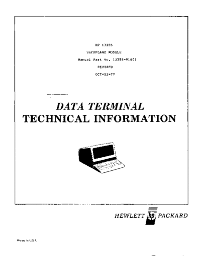
Image preview - the first page of the document

>> Download 13255-91001_Backplane_Module_Oct77 documenatation <<
Text preview - extract from the document
                             HP 13255

                         BACKPLANE MODULE
                     Manual Part No. 13255-91001

                              REVISED
                             OCT-12-77


         DATA TERMINAL
     TECHNICAL INFORMATION


                                         HEWLETT~PACKARD


Printed iin U.S.A.
13255                                                                        13255-91001/02
Backplane Module                                                             Rev OCT-12-77


1.0        INTRODUCTION.
           This section contains design and application information for the Back-
           plane Module and establishes the rules for interfacing between the
           various functional modules and the backplane (terminal data bus).
           The backplane is a printed-circuit board mounted to the bottom of the
           terminal base and contains a power supply connector and a number of
           printed circuit edge connectors. In addition to providing power to
           the functional modules, it supplies the 4.915 MHz System Clock (SYS
           CLK) and System Power On (PWR ON) signals. Data, address, and control
           signals for communication between the various functional modules is
           is also supplied by the Backplane MOdule. The bus is the primary data
           path between the processor and memory, display and memory, and the
           processor and peripherals (such as the keyboard, data comm, display,
           printer, and the CTU). All communication on the bus occurs in a
           serially shared mOde, with each byte transfer being an independent
           non-interruptaole transaction.

2.0        OPERATING PARAMETERS.
           A summary of operating parameters for the Backplane Module is contained
           in tables 1.0 through 3.2.

                             Table 1.0    Physical Parameters

---------------------------------~--~-----------~------~--------~---~-----~-~---
-------------~ --------------------------~---~--------~----~----------~-~-------
     Part                                         Size (
◦ Jabse Service Manual Search 2024 ◦ Jabse Pravopis ◦ onTap.bg ◦ Other service manual resources online : Fixya ◦ eServiceinfo