Service Manuals, User Guides, Schematic Diagrams or docs for : Keithley 199 199_901_01D
<< Back | HomeMost service manuals and schematics are PDF files, so You will need Adobre Acrobat Reader to view : Acrobat Download Some of the files are DjVu format. Readers and resources available here : DjVu Resources
For the compressed files, most common are zip and rar. Please, extract files with Your favorite compression software ( WinZip, WinRAR ... ) before viewing. If a document has multiple parts, You should download all, before extracting.
Good luck. Repair on Your own risk. Make sure You know what You are doing.
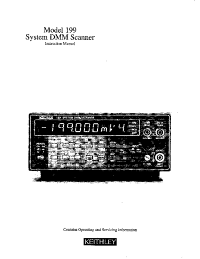
Image preview - the first page of the document

>> Download 199_901_01D documenatation <<
Text preview - extract from the document
      Model 199
System DMM Scanner
     Instruction Manual


               Contains Operating and Servicing Information
                                                          WARRANTY
Keithley Instruments,   Inc. warrants tbis product to be free from defects in material and workmanship   for a period of 1 year from date of
shipment.


Keithley Instruments, Inc. warrants the following   items for 90 days from the date of shipment:    probes, cables, rechargeable   batteries,
diskettes, and documentation.


During the warranty period, we will, at our option, either repair or replace any product that proves to be defective.


To exercise this warranty, write or call your local Keithley representative, or contact Keithley headquarters in Cleveland, Ohio. You will
be given prompt assistance and return instructions. Send the product, transportation prepaid, to the indicated service facility. Repairs
will be made and the product returned, transportation prepaid. Repaired or replaced products are warranted for the balance of the origi-
nal warranty period, or at least 90 days.


                                                LIMITATION          OF WARRANTY

This warranty does not apply to defects resulting froti~product modification without Keitbley's express written consent, or misuse of
any product ox-part. This warranty also does not apply to fuses, software, non-rechargeable batteries, damage from batteIy leakage, or
problems arising from normal wear or failure to follow instmctions.


THIS WARRANTY IS IN LIEU OF ALL OTHER WARRANTIE S, EXPRESSED OR IMPLIED. INCLUDING ANY IMPLIED
WARRANTY OF MERCHANTABILITY    OR FITNESS FOR A PARTICULAR USE. THE REMEDIES PROVIDED HEREIN ARE
BUYER'S SOLE AND EXCLUSIVE REMEDIES.


NEITHER KZITHLEY INSTRUMENTS,   INC. NOR ANY OF ITS EMPLOYEES SHALL BE LIABLE FOR ANY DIRBCT, INDI-
RECT, SPECIAL, INCIDENTAL OR CONSEQUENTIAL   DAMAGES ARISING OUT OF THE USE OF ITS INSTRUMENTS AND
SOFTWARE EVEN IF KEITHLEY INSTRUMENTS,     INC., HAS BEEN ADVISED IN ADVANCE OF THE POSSIBILITY  OF
SUCH DAMAGES. SUCH EXCLUDED DAMAGES SHALL INCLUDE, BUT AR!? NOT LIMITED TO: COSTS OF REMOVAL
AND INSTALLATION, LOSSES SUSTAINED AS THE RESULT OF INJURY TO ANY PERSON, OR DAMAGE TO PROPERTY.
Model   199 System DMM Scanner
        Instruction Manual


          0 1988, Keith& Instruments, Inc
             Test Instrumentation Group
                 All rights reserved.
              Cleveland, Ohio, U.S.A.
             July 1987, Fourth Printing
        Document Number: 199-901-01 Rev. D
                                 SAFETY            PRECAUTIONS

The following   safety precautions    should be observed    before operating   the Model 199.


This instrument is intended for use by qualified ~personnel who recognize shock hazards and are familiar
with the safety precautions required to avoid possible injury. Read over the manual carefully before operating
this instrument.


Exercise extreme caution when a shock hazard is present at the instrument's input. The American National
Standards Institute (ANSI) states that a shock hazard exists when voltage levels greater than 3OV rms or
42.4V peak are present. A good safety practice is to expect that a hazardous voltage is present in any unknown
circuit before measuring.


Inspect the test leads for possible wear, cracks or breaks before each use. If any defects are found, replace
the test leads.


For optimum safety do not touch the test leads or the instrument while power is applied to the circuit under
test. Turn the power off and discharge all capacitors, before connecting or disconnecting the instrument.
Always disconnect all unused test leads from the instrument.


Do not touch any object which could provide a current path to the common side of the ,+cuit under test
or power line (earth) ground. Always make measurements     with dry hands while standmg on a dry, in-
sulated surface, capable of withstanding the voltage being measured.


Exercise extreme safety when~ testing high energy power circuits (AC line or mains, etc). Refer to the High
Energy Circuit Safety Precautions found in paragraph 2.6 (Basic Measurements).


Do not exceed the instrument's       maximum   allowable   input as defined in the~specifications   and operation
section.
           cw%a   wi) sdw   3a
;.,   ,,
           MAXIMUM            READING          RATES    (Readings/Second)'             STORAGE        & SCANNING                CAPABILITIES

                                                                                      SO&Reading Memory:         Stores    reading, range, and
                                                                                        scanner channel.
                                                                                      Trigger: One shot or continuous from front pane,,
                                                                                         IEEE.488 bus. and rear panel BNC.
                                                                                       Programmable    Reading    Interval:      15ms to 999.999s.
                                                                                       Programmable    Trigger Delay:      Ims to 999.9995.

                                                                                      WITH MODEL        1992 &CHANNEL              SCANNER
                                                                                      Pmgmmmable       Configuration:       t    or 4-pole.
                                                                                      Fmgrammable      Channel    Limit:      1 to 8.
                                                                                      Pmgnmmable       Scanning    Moder:        Manual, step,
                                                                                       and scan.
                                                                                       Ratio: Channels 2 thmugh 8 referenced to Channel 1.


           IEEE-488     BUS IMPLEMENTATION                                      GENERAL
           MULTILINE COMMANDS:            DCL, LLO. SDC, GET, GTL,              MAXIMUM      READING:     302,999 cmmts in SK-digit mode.
            UNT, UNL, SPE. SPD.
                                                                                CONNECTORS:       Measurement:  Switch selectable front or
           UNlLiNE     COMMANDS:       IFC, REN, EOI, SRQ. ATN.                  rear, safety jacks. DigitaL TRIGGER input and METER
           INTERFACE FUNCIlONS:          SHl, AHI, T6, TFQ, L4, LEO,             COMPLET!? output on rear panel, BNCr.
           SRl, RLI. PPO, DCl, DTl,     CD. El.                                 WARMUP:     2 hours to rated accuracy.
           All front pane, functions and programs are available over
                                                                                TEMPERATURE      COEFFICIENT    ,04-18'C & 28'-50'0:
           the IEEE-488 bus, in addition to Status, Swice Request, Out-
                                                                                  c t(O.1 x applicable accuracy sp&fication)l
◦ Jabse Service Manual Search 2024 ◦ Jabse Pravopis ◦ onTap.bg ◦ Other service manual resources online : Fixya ◦ eServiceinfo