Service Manuals, User Guides, Schematic Diagrams or docs for : Keithley 2450 071314000 (June 2013)(Model 2450-TLINK)
<< Back | HomeMost service manuals and schematics are PDF files, so You will need Adobre Acrobat Reader to view : Acrobat Download Some of the files are DjVu format. Readers and resources available here : DjVu Resources
For the compressed files, most common are zip and rar. Please, extract files with Your favorite compression software ( WinZip, WinRAR ... ) before viewing. If a document has multiple parts, You should download all, before extracting.
Good luck. Repair on Your own risk. Make sure You know what You are doing.
Image preview - the first page of the document

>> Download 071314000 (June 2013)(Model 2450-TLINK) documenatation <<
Text preview - extract from the document
                                                                                Model 2450-TLINK
Keithley Instruments, Inc.
28775 Aurora Road
                                                                                   Trigger Link Cable
Cleveland, Ohio 44139
1-888-KEITHLEY
http://www.keithley.com


Description
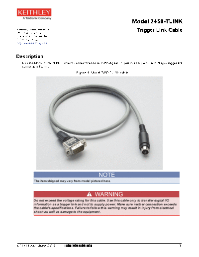
   Use the Model 2450-TLINK cable to connect the Model 2450 digital I/O port to an 8-pin micro DIN type trigger link
   connector (TLINK).
                                         Figure 1: Model 2450-TLINK cable


            The item shipped may vary from model pictured here.


            Do not exceed the voltage rating for this cable. Use this cable only to transfer digital I/O
            information as a trigger link and not to supply power. Make sure neither connection exceeds
            the cable's specifications. Failure to follow this warning may result in injury from electrical
            shock as well as damage to the equipment.


071314000 / June 2013           *P071314000*                                                                     1
Model 2450-TLINK


Characteristics
    Length: 36 in. (91.5 cm)
    Voltage rating: 42 V (peak)
    Maximum current: 1 A
                                  Figure 2: Model 2450-TLINK schematic


2                                                                        071314000 / June 2013
                                                                                                     Model 2450-TLINK


Connection instructions
  The following figure shows a typical Model 2450-TLINK connection. When connected, you can use any of the six
  TLINK lines to send or read TTL signals.
  The following connection example controls measurements using TTL LO signals over lines 1 and 2. Configure the
  Model 2450 to take measurements when a signal is read on digital I/O port pin 2; configure it to send a signal on
  digital I/O port pin 1 when it is finished measuring. Configure the other instrument (the one with the TLINK
  connector) to send the start signal on digital I/O port pin 2 and to read the completion signal from digital I/O port
  pin 1.


          You must configure which measurements the Model 2450 makes when triggered. You must also
          configure the TLINK instrument to perform any needed actions before it triggers the Model 2450 and
          any subsequent actions after it receives the completion signal.

          Refer to the Model 2450 Reference Manual for specific trigger link, trigger model, and digital I/O
          information. For configuration of the other instrument, refer its documentation.


                          Figure 3: Model 2450-TLINK cable connection to Model 2450


071314000 / June 2013                                                                                               3
Model 2450-TLINK


 Model 2450-TLINK connection pinouts
Trigger link       Trigger link           Digital I/O pin ** Port description
connector pin
1*                 Line #1                1                  I/O
2*                 Line #2                2                  I/O
3                  Line #3                3                  I/O
4                  Line #4                4                  I/O
5                  Line #5                6                  I/O
6                  Line #6                8                  I/O
7                  Digital common         9                  Ground
8                  Digital common

* Used in example
** Pin 5 and pin 7 of the Model 2450 digital I/O are not connected


 4                                                                              071314000 / June 2013
◦ Jabse Service Manual Search 2024 ◦ Jabse Pravopis ◦ onTap.bg ◦ Other service manual resources online : Fixya ◦ eServiceinfo