Service Manuals, User Guides, Schematic Diagrams or docs for : Keithley 2510 pa791a(Model2510_252C2510AT)
<< Back | HomeMost service manuals and schematics are PDF files, so You will need Adobre Acrobat Reader to view : Acrobat Download Some of the files are DjVu format. Readers and resources available here : DjVu Resources
For the compressed files, most common are zip and rar. Please, extract files with Your favorite compression software ( WinZip, WinRAR ... ) before viewing. If a document has multiple parts, You should download all, before extracting.
Good luck. Repair on Your own risk. Make sure You know what You are doing.
Image preview - the first page of the document

>> Download pa791a(Model2510_252C2510AT) documenatation <<
Text preview - extract from the document
                                                       Models 2510 and 2510-AT Connector Label
Keithley Instruments, Inc.
28775 Aurora Road                                                                  Packing List
Cleveland, Ohio 44139
(440) 248-0400


Introduction
This packing list contains information about the supplied INPUT/OUTPUT connector label, which can be used to properly
identify OUTPUT connection polarity when using the Model 2510/2510-AT with certain TECs.


Output current convention
The Models 2510 and 2510-AT assume that a positive output current is heating current. However, industry convention is that a
positive TEC current is a cooling current. For proper operation with such TECs, it is recommended that you install the supplied
label and reverse TEC connections as discussed below.


Label installation
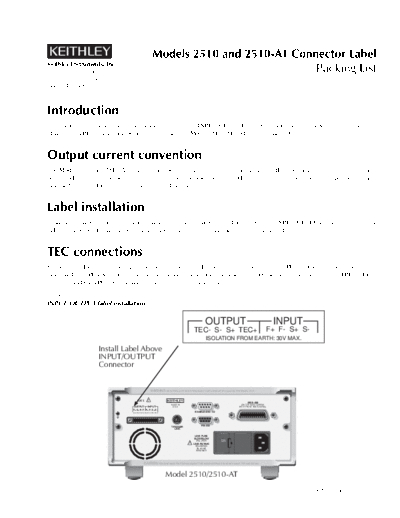
To install the label, remove the backing and then install the label immediately above the INPUT/OUTPUT connector as shown
in Figure 1 below. Be sure to position the label so that the terminals are correctly identified.


TEC connections
For positive TEC current cooling convention, connect the TEC positive terminal to the OUTPUT TEC+ terminal shown on the
label (and OUTPUT S+ terminal when using 4-wire connections). Connect the TEC negative terminal to the OUTPUT TEC-
terminal (and OUTPUT S- terminal when using 4-wire connections).

Figure 1
INPUT/OUTPUT label installation

                                                                                                 OUTPUT                                             INPUT
                                                                                        TEC- S- S+ TEC+                                         F+ F- S+ S-
                                                                                                  ISOLATION FROM EARTH: 30V MAX.

                   Install Label Above
                   INPUT/OUTPUT
                   Connector


                                                      WARNING:NO INTERNAL OPERATOR SERVICABLE PARTS,SERVICE BY QUALIFIED PERSONNEL ONLY.


                                     CAT I        !
                                                                                                                                  IEEE-488
                                                                      MADE IN                                               (ENTER IEEE ADDRESS
                                 OUTPUT           INPUT                U.S.A.                                              WITH FRONT PANEL MENU)
                                 F+ S+ S- F- F+ F- S+ S-
                                 ISOLATION FROM EARTH: 30V MAX.
                                                                                         ENABLE-DIG I/O


                                                                      TRIGGER                 RS-232
                                                                        LINK

                                                                                         LINE FUSE
                                                                                        SLOWBLOW
                                                                                         2.5A, 250V
                                                                                                              120

                                                                                    !   LINE RATING
                                                                                         100-240VAC
                                                                                          50, 60 HZ
                                                                                          90VA MAX


                                             CAUTION:FOR CONTINUED PROTECTION AGAINST FIRE HAZARD,REPLACE FUSE WITH SAME TYPE AND RATING.


                                                                  Model 2510/2510-AT

                                                                                                                                                              PA-791 Rev. A / 5-01
2
◦ Jabse Service Manual Search 2024 ◦ Jabse Pravopis ◦ onTap.bg ◦ Other service manual resources online : Fixya ◦ eServiceinfo