Service Manuals, User Guides, Schematic Diagrams or docs for : Keithley 500 500_916_01C
<< Back | HomeMost service manuals and schematics are PDF files, so You will need Adobre Acrobat Reader to view : Acrobat Download Some of the files are DjVu format. Readers and resources available here : DjVu Resources
For the compressed files, most common are zip and rar. Please, extract files with Your favorite compression software ( WinZip, WinRAR ... ) before viewing. If a document has multiple parts, You should download all, before extracting.
Good luck. Repair on Your own risk. Make sure You know what You are doing.
Image preview - the first page of the document
>> Download 500_916_01C documenatation <<
Text preview - extract from the document
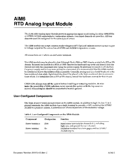
RTD Analog Input Module
           The AIM6 RTD Analog Input Module provides appropriate signal conditioning for either 1OOQRTDs
           or AD59O/AC2626 semiconductor temperature sensors. Four input channels are provided. All four
           channels must be configured for the same type of sensor.


           The AIM6 module can accept common mode voltages to rtGV Optional resistors convert current output
           to voltage output for the connection of AD590 and AC2626 temperature sensors.


           All connections are made to on-card screw terminals.


                                                                                   -^^- .
           The AiM6 module may be piaced in siots 2 through i0 of a 500A or 5UW chassis, or siot 3 of a 575 or 576
           chassis. To install the module in a 500A or 5OOP,remove the baseboard top cover and insert it into the
           desired slot with the component side facing the power supply. To minimize temperature effects from
           the power supply and to keep noise pickup to a minimum, it is recommended that the AIM6 module
           be installed as close to the AMM module as possible. Generally, analog modules should be placed in the
           low-numbered slots while digital modules should be placed in the high-numbered slots to minimize
           these effects. For installation into a 575 or 576 chassis, consult the hardware manual for that chassis.


           CAUTION: Always turn off the system before installing or removing modules. To min-
           imize the possibility of EMI radiation, never operate the system with the top cover re-
           moved. Unused inputs should be connected to module ground.


User-Configured         Components

           One bank of screw terminals is provided on the AIM6 module. In addition to high (+>, low (-1 and
           ground terminals, the AIM6 module has a single terminal to provide a +lOV excitation for AD590/
           AC2626 temperature sensors. A potentiometer allows adjustment of the excitation voltage.


           Table 1. User-Configured          Components   on the AIM6 Module

            Component                 Designation         Function

            Screw terminals       J164                    Input screw terminals for channels O-3, including
                                                          high, low, and ground for each channel.
            Screw terminal            E-I-                Excitation terminal for strain gages and/or AD590/
                                                          AC2626 inputs.


Document Number: 500-916-01 Rev. C                                                                             AIMG-1
         Figure 1. AIM6 Module       Configuration


         Connections

         Terminals for the four channels available on the AIM6 are marked on the module board. A typical con-
         nection is illustrated in Figure 2. All terminals accept 16-24 gage wire, stripped to 3/16 of an inch.


         CAUTION:      The use of shielded   cable is recommended      to minimize   the possibility    of EM1 radiation.


         E+ is a single screw terminal which provides a +lOV excitation source for AD590/AC2626 temperature
         sensors connected to the AIM6 module. Information on connecting these devices to the excitation ter-
         minal is covered in the following section.


         Excitation   for RTDs is not provided   for by this terminal, but by the signal conditioning     circuitry   of the
         module.


         Strain Gauges

         The AIM6 can be used to measure strain gauges. Figure 2 below details the strain gauge bridge connec-
         tions.


         Note: Strain gauge channels can be mixed with AD590 channels on an AlM6. However, neither strain
         gauge nor AD590 channels can be mixed with RTD channels on the same AIM6. KDAC500 software
         does not support engineering units conversion of strain gauge data on the AIh46. The programmer must
         convert the raw voltage readings of the AMM module to engineering units.


AJM6-2
                                                                         Signal+


                                       J164


 Figure 2. AIM6 STRAIN     GAUGE Connection       (Channel   0 shown)


Current to Voltage Conversion

By installing optional resistors each channel can be modified to accept current input from AD590/
AC2626 temperature sensors. These resistors can be installed between the high (-I->and low (-1 input ter-
minals, for each channel of current input.


A 21OQ resistor is recommended    for the temperature   sensor inputs. The resulting   voltage output is de-
termined by Ohm's law:

E=I*R
Voltage (volts) = Current (amps) * Resistance (ohms)


Resistance Temperature    Detectors (RTDs)

The most common type of RTD is the platinum resistance thermometer, simply a coil of very pure plat-
inum wire calibrated to have a known resistance (often 1OOQ) at 0
◦ Jabse Service Manual Search 2024 ◦ Jabse Pravopis ◦ onTap.bg ◦ Other service manual resources online : Fixya ◦ eServiceinfo