Service Manuals, User Guides, Schematic Diagrams or docs for : LG Mobile Phone LG G7020 LG G7020 4
<< Back | HomeMost service manuals and schematics are PDF files, so You will need Adobre Acrobat Reader to view : Acrobat Download Some of the files are DjVu format. Readers and resources available here : DjVu Resources
For the compressed files, most common are zip and rar. Please, extract files with Your favorite compression software ( WinZip, WinRAR ... ) before viewing. If a document has multiple parts, You should download all, before extracting.
Good luck. Repair on Your own risk. Make sure You know what You are doing.
Image preview - the first page of the document

>> Download LG G7020 4 documenatation <<
Text preview - extract from the document
                                                           8. DISASSEMBLY INSTRUCTION


8. DISASSEMBLY INSTRUCTION
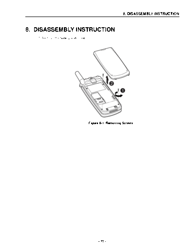
   1. Remove the battery and screws.


                                                      2
                                                           1


                                       Figure 8-1. Removing Screws


                                             - 77 -
8. DISASSEMBLY INSTRUCTION


      2. Use a thin plastic sheet to slide and open the gap between front and rear covers, and detach
         them carefully with both hands.

      3. Then carefully remove the rear cover from the hooks as shown in Figure 8-2.


                                                                                                  1
                                     2
                      1

                                                                                                        2


                                       Figure 8-2. Disassembling covers

      4. Unlock the PCB and remove other components as shown in Figure 8-3.


                                 Figure 8-3. Unlocking and removing the PCB


                                                - 78 -
                                                         8. DISASSEMBLY INSTRUCTION


5. Firstly, insert one side of FPCB carefully into the slot.
   Then place the PCB under the hook 1 first and push the other end of PCB under the hook 2


                                        1
                          2


                          Figure 8-4. Assembly of PCB with the cover


                                         - 79 -
8. DISASSEMBLY INSTRUCTION


      6. Remove the antenna and use a sharp awl to push away the antenna-bushing.


                                                          1


                                                          2


                                                      3


                                  Figure 8-5. Removing antenna-bushing


                                             - 80 -
                                                            8. DISASSEMBLY INSTRUCTION


7. Use a tweezers to remove the battery locker.


               1
                            1
                2


                                                                    3


                                Figure 8-6. Removing battery locker

8. When removing the side button from the main front, please see the insert-nut next to the button
   and carefully remove it.


                                                             Insert-nut


                                Figure 8-7. Removing a side button


                                          - 81 -
8. DISASSEMBLY INSTRUCTION


      9. Push away the hinge to remove the folder.


                                         Figure 8-8. Removing Folder

      10. Remove the hinge, and detach screw caps by using a pin.


                                   Figure 8-9. Removing hinge and screws


                                               - 82 -
                                                            8. DISASSEMBLY INSTRUCTION


11. Use a thin plastic sheet to slide and open the gap between the folders.
    Then detach them carefully with both hands.


                                Figure 8-10. Disassembling Folders


                                           - 83 -
8. DISASSEMBLY INSTRUCTION


      12. Finally detach the rest components as shown in Figure 8-11.


                              Figure 8-11. Disassembly of the rest components


                                               - 84 -
◦ Jabse Service Manual Search 2024 ◦ Jabse Pravopis ◦ onTap.bg ◦ Other service manual resources online : Fixya ◦ eServiceinfo