Service Manuals, User Guides, Schematic Diagrams or docs for : LG Monitor 1468 CH480_6B
<< Back | HomeMost service manuals and schematics are PDF files, so You will need Adobre Acrobat Reader to view : Acrobat Download Some of the files are DjVu format. Readers and resources available here : DjVu Resources
For the compressed files, most common are zip and rar. Please, extract files with Your favorite compression software ( WinZip, WinRAR ... ) before viewing. If a document has multiple parts, You should download all, before extracting.
Good luck. Repair on Your own risk. Make sure You know what You are doing.
Image preview - the first page of the document

>> Download CH480_6B documenatation <<
Text preview - extract from the document
                                         R,G,B                       R,G,B                     R,G,B
                  SIGNAL
                                                     Video Drive                Video Output
         PC                                                                                                     TUBE
                                                     Circuit                    Circuit
                               V-Sync.     H-Sync.


                                                                                                       Screen

             2nd Rectifier
             Circuit

                                                      Mode Control           Vertical Output                           Anode
             Transformer                              Circuit                Circuit


-9-
                                                                                  V
       Primary             Switching
                                                                                                                               BLOCK DIAGRAM


       Rectifier           Control
       Circuit             Circuit                                                     H                 High Voltage
                                                              Horizontal / Vertical                      Generation Circuit
                                                              Drive Circuit
              E

         L        N


      AC LINE VOLTAGE
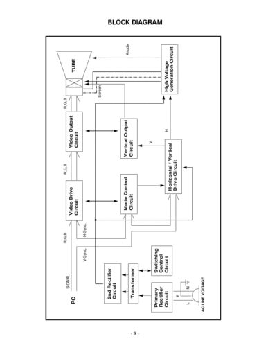
DISCRIPTIONS OF BLOCK DIAGRAM
1. PRIMARY RECTIFIER CIRCUIT
    This is a circuit that transform a AC (line voltage) of wall to DC voltage as the supplied source in chassis.
    It is operated by C904 (electrolytic capacitor) and D901 (bridge diode).

2. SWITCHING CONTROL CIRCUIT
    This block operate to be kept the outputs of the 2nd rectified circuit in constant level in any conditions.
    : no load, full load, line voltage variation, etc.
    The main function is operated by IC901 (STR5717) syncronizing to H-frequency via a connector that tie
    around the core of the FBT (T702).

3. 2nd RECTIFIER CIRCUIT
    This block rectifying the pulse waveform of the transformer generated by switching control circuit.
    It is consisted of capacitor and diode.
    The output voltages are 125V, 95V, 70V, 40V, 12V and 6.3V that are necessary to the chassiss operation.

4. VIDEO DRIVE CIRCUIT
    This block is pre-amplify the video signal (Red, Green and Blue) of PC to make sufficient signal of the video
    output circuit.
    The function is operated by IC301 (TDA4881/2).

5. VIDEO OUTPUT CIRCUIT
    This block amplify the pre-amplified signal through the video drive circuit to drive the CDT (Cathode Display
    Tube). The cascode amplify stages and buffer stages of each color are used to this block and the drive
    transistor of cascode amplifier lies inside of the IC301. The buffer stages are consist of PNP and NPN type of
    transistor.

6. MODE CONTROL CIRCUIT
    This block generate the signal need to control the function of the horizontal and vertical drive circuit.
    The function is operated IC201 (Gate Array) by combination of the horizontal and the vertical sync signal.

7. HORIZONTAL/VERTICAL DRIVE CIRCUIT
    This block manage the function, that are H/V-position, side pincushion and H/V-hold, with the output signal of
    mode control circuit. The generated vertical signal is applied to the vertical output circuit.
    The generated horizontal signal is applied to the high voltage generation circuit that supply the operating
    voltage of CDT (Cathode Display Tube). These are controlled by the circuit in and around IC701.

8. VERTICAL OUTPUT CIRCUIT
    This block generate the signal to deflect the beam of CDT vertically.
    IC601 control the waveform of deflection.

9. HIGH VOLTAGE GENERATION CIRCUIT
    This block generate the voltages to operate CDT and produce the horizontal deflection energy via a Q706 and
    T702 (FBT).
    The high voltage is about 24kV for anode, 6kV for focus and 550V for screen of the CDT.


                                                         - 10 -
◦ Jabse Service Manual Search 2024 ◦ Jabse Pravopis ◦ onTap.bg ◦ Other service manual resources online : Fixya ◦ eServiceinfo