Service Manuals, User Guides, Schematic Diagrams or docs for : LG Monitor sw56i CS580_10
<< Back | HomeMost service manuals and schematics are PDF files, so You will need Adobre Acrobat Reader to view : Acrobat Download Some of the files are DjVu format. Readers and resources available here : DjVu Resources
For the compressed files, most common are zip and rar. Please, extract files with Your favorite compression software ( WinZip, WinRAR ... ) before viewing. If a document has multiple parts, You should download all, before extracting.
Good luck. Repair on Your own risk. Make sure You know what You are doing.
Image preview - the first page of the document

>> Download CS580_10 documenatation <<
Text preview - extract from the document
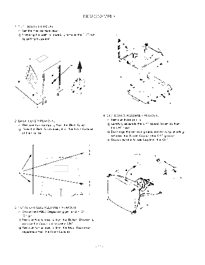
                                                 DISASSEMBLY

1. TILT/SWIVEL REMOVAL
      Set the monitor face down.
      Pressing the latch , carefully remove the Tilt/Swivel
      by pulling it upward.


                                                                   4. CRT BOARD ASSEMBLY REMOVAL
2. BACK COVER REMOVAL                                                   Remove three pins .
     Remove four screws     from the Back Cover.                        Carefully separate the CRT Board Assembly from
     Slide the Back Cover away from the Front Cabinet                   the CRT neck.
     of the monitor.                                                    Discharge the remaining static electricity by shorting
                                                                        between the Anode Cap and the CRT ground.
                                                                        Disconnect the Anode Cap from the CRT


                                                                                       Anode cap


3. TOTAL CHASSIS ASSEMBLY REMOVAL
     Disconnect P902(Degaussing pin) and P701
     (DY pin).
     Remove five screws      from the Bottom Bracket to
     remove the Ground Wire of the CRT.
     Remove two screws       from the Main Bracket to
     separate it from the Front Cabinet.


                                                              - 11 -
5. BOTTOM BRACKET REMOVAL              6. MAIN BOARD ASSEMBLY REMOVAL
     Remove two screws .                    Remove three screws .
     Remove the Bottom Bracket.             Remove three screws .
                                            Release four latches from the Main Board
                                            Assembly.


        Bottom bracket


                                  - 12 -
◦ Jabse Service Manual Search 2024 ◦ Jabse Pravopis ◦ onTap.bg ◦ Other service manual resources online : Fixya ◦ eServiceinfo