Service Manuals, User Guides, Schematic Diagrams or docs for : LG Monitor sw56i CS580_4

<< Back | Home

Most service manuals and schematics are PDF files, so You will need Adobre Acrobat Reader to view : Acrobat Download Some of the files are DjVu format. Readers and resources available here : DjVu Resources
For the compressed files, most common are zip and rar. Please, extract files with Your favorite compression software ( WinZip, WinRAR ... ) before viewing. If a document has multiple parts, You should download all, before extracting.
Good luck. Repair on Your own risk. Make sure You know what You are doing.


Image preview - the first page of the document
CS580_4


>> Download CS580_4 documenatation <<

Text preview - extract from the document
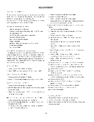
                                                  ADJUSTMENT
GENERAL INFORMATION

All adjustment are thoroughly checked and corrected                      Adjust H-position as center of the screen.
when the monitor leaves the factory, but sometimes                       Adjust V-size as 190 1mm.
several minor adjustment may be required.                                Adjust V-position as center of the screen.
Adjustment should be following procedure and after                       Adjust side-pincushion (east-west), trapezoid distortion,
warming up for a minimum of 30 minutes.                                  and tilt should be the best condition.
                                                                  3. Adjustment for the White Balance and Luminance as
  Alignment appliances and tools                                     follows:
  - IBM compatible PC & Monitor.                                         Set the White Balance Meter.
  - Programmable Signal Generator (eg. VG-819 made                       Press the      button for demagnetized CRT of the
     by Astrodesign Co.)                                                 monitor.
  - E(E)PROM with saved each mode data.                                  Display color 0,0 pattern at Mode 6.
  - Oscilloscope with probe                                              Set Brightness and VR802 (Sub-Bright) volume to
  - Alignment cable with adaptor                                         Max position.
  - Digital Voltmeter                                                    Set Contrast to Max and Sub-Contrast to center
  - Software (Alignment program for this monitor)                        position.
  - White Balance Meter                                                  Set VR301 (R-Bias) and VR302 (G-Bias) to Min
  - Luminance Meter                                                      position.
                                                                         Adjust Screen control of the FBT to 0.1FL of the raster
AUTOMATIC AND M ANUAL DEGAUSSING
                                                                         luminance.
The degaussing coil is mounted around the CRT so that
external degaussing is normally unnecessary after turn                   Adjust VR301 (R-Bias) and VR302 (G-Bias) to
on the monitor. But the monitor is moved or faced in a                   x=0.281 0.015 and y=0.311 0.015.
different direction, become poor color purity cause of CRT               Adjust VR802 (Sub-Bright) to 0.3 0.1FL of the
magnetized, then press        (DEGAUSSING) button to                     raster luminance.
remove color purity problem.                                             Display color 15,0 box pattern (70x70mm) at Mode 6.
                                                                         Adjust R-DRIVE 1, G-DRIVE 1, and B-DRIVE 1 to
B+ ADJUSTMENT
                                                                         x=0.281 0.003 and y=0.311 0.003 with arrow keys.
1. Display cross hatch pattern at Mode 2.                                Save in the COLOR 1 .
2. Adjust D955 cathode voltage to 50 0.2V with VR951.                    Adjust SUB-CONTRAST 1 to 60 1FL of the box
                                                                         pattern luminance.
HIGH VOLTAGE ADJUSTMENT                                                  Adjust R-DRIVE 2, G-DRIVE 2, and B-DRIVE 2 to
1. Display cross hatch pattern at Mode 2.                                x=0.297 0.003 and y=0.320 0.003 with arrow keys.
2. Adjust D713 cathode voltage to 42.5 0.2V with VR501.                  Save in the COLOR 2 .
                                                                         Adjust SUB-CONTRAST 2 to 60 1FL of the box
RASTER CENTER ADJUSTMENT.                                                pattern luminance
1. Display cross hatch pattern at Mode 6.                                Display color 15,0 full white pattern at Mode 6.
2. Set the Brightness to Max position that the back raster               Adjust ABL to 30 1FL of the luminance.
   should be visible.                                                    Exit from the program.
3. Select the H-center switch (SW701) to the raster should
  be center of the screen.
                                                                  FOCUS ADJUSTMENT.
IMAGE OF SCREEN AND WHITE BALANCE ADJUSTMENT                      1. Set the Brightness and Contrast to Max position.
1. Install the cable for adjustment such as figure 1.             2. Display H character in full screen at Mode 6.
2. Run the software delivered from LG Electronics Inc. for        3. Adjust Focus control on the FBT that the focus should be
   the special adjustment.                                           the best condition.
      Display cross hatch pattern from Mode 1 to Mode 6.
      Adjust H-size as 260 1mm.


                                                             - 16 -
          Monitor to be
          Adjustment


                                                                 Parallel Port
                                                                                         A
                                                                                                                        C


                                                                                         11
                                                                                  15
                                            IBM


                                                                                  5 10


                                                                                              6
                                                                                             1
                                            Compatible PC
Video
                                                                                                  13                                        1
Signal Generator                                                                                   25                                      14
               Control Line


                              A

                              Adapter   C                                                                               5V

                                                                                                                             4.7K


                                                                                  15


                                                                                             11
                                                                                                        5V                          4.7K


                                                                                 10


                                                                                              6
                                                                                                                             74LS06


                                                                                  5
                                                                                                        4.7K     4.7K
                              B


                                                                                         1
                                                                                                        74LS06


                                                                                         B


                                        FIGURE 1, CABLE CONNECTION


                                                        - 17 -


◦ Jabse Service Manual Search 2024 ◦ Jabse PravopisonTap.bg ◦ Other service manual resources online : FixyaeServiceinfo