Service Manuals, User Guides, Schematic Diagrams or docs for : LG Audio FL-R888K FL-R88~2

<< Back | Home

Most service manuals and schematics are PDF files, so You will need Adobre Acrobat Reader to view : Acrobat Download Some of the files are DjVu format. Readers and resources available here : DjVu Resources
For the compressed files, most common are zip and rar. Please, extract files with Your favorite compression software ( WinZip, WinRAR ... ) before viewing. If a document has multiple parts, You should download all, before extracting.
Good luck. Repair on Your own risk. Make sure You know what You are doing.


Image preview - the first page of the document
FL-R88~2


>> Download FL-R88~2 documenatation <<

Text preview - extract from the document
                                             ADJUSTMENTS
This set has been aligned at the factory and normally will not require further adjustment. As a result, it is not
recommended that any attempt is made to modificate any circuit. If any parts are replaced or if anyone tampers      -
with the adjustment, realignment may be necessary.


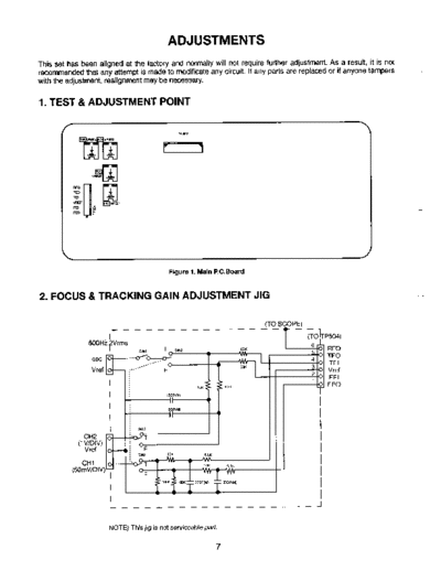
1. TEST & ADJUSTMENT POINT


                                                 PNS02


                                              Figure 1. Main l?C.Boatd


                                                                                                                    -
2. FOCUS & TRACKING GAIN ADJUSTMENT                                              JIG

                                                                                   (TO SCOPE)

                        I
                800H12Vrms                                                             -r


                                                                                       fa
                                                                                            1       RF0
                                                                                                    TEO
                 osc                                                                            4
                                                                                                    TEI
                                                                                                3
                 Vref                                                                               Vref
                                                                                                2
                                                                                                4    FEI
                                                                                                    FE0


               CH2
            (1 VIDIV)
               Vref

             CHI
          (SOmWDIV)
                                                            " _
                                                            .`PK       .6..8.~


                        NOTE) This jig is not serviceable   pat?.


                                                                   7
3. Before    adjusting,     preset   adjustment    potentiometers    VR501,    VR502,        VR503   and   VR504
   center.
                                                                       L
4. TRACKING BALANCE ADJUSTMENT                                        .s`
   1) Connect the oscilloscope to TP504 (pin @ : TEO) and TP504 (pin @ : Vref).
   2) Insert the test disc (YEDS-18) and playback the 12th selection.
   3) Turn VR502 fully counter-clockwise.
   4) Adjust VR504 so that the amplitude above and below the zero DC line becomes equal (amplitude A=B).


                                                    A=B
    5) Set VR502 to center position.

5. FOCUS OFFSET ADJUSTMENT (you have to use 1O:l                       probe)
   1) Connect the oscilloscope to TP504 (RFO) and TP504 (Vref).
   2) Adjust VR501 so that eye pattern becomes clear and waveform (Vp-p) is maximum.
   3) Confirm the oscilloscope reading.
      i ) Less than 200mV - OK
      ii ) More than 200mV - readjust VR501 200mV.


                          Good adjustment                                     d adjustment
                                                  EYE PATTERN


6. FOCUS, TRACKING GAIN ADJUSTMENT (with Jig)
   1) Connect the gain adjustment jig to TP504.
   2) Connect the audio frequency oscillator the A.F.OSC terminal on the gain adjustment jig.
      Set the audio frequency oscillator output to 800Hz 2Vrms.
   3) Set the gain adjustment jig with oscilloscope to below.
       i ) CHl : SOmV/div, AC mode
      ii ) CH2 : lV/div, AC mode


   6-V   FOCUS GAIN ADJUSTMENT
         Set switch SW2 on the gain adjustment jig to position `lF".
         Adjust VR503 so that the waveform on the oscilloscope looks as shown below.


           Good adjustment                         Bad adjustment                     Bad adjustment
         (Optimum focus gain)                     (Low focus gain)                   (High focus gain)

                                                          8
  6-2) TRACKING       GAIN ADJUSTMENT
       Set switch SW2 on the gain adjustment jig to position "T".
       Adjust VR502 so that the waveform on the oscilloscope looks as shown below.


         Good adjustment                      Bad adjustment                          Bad adjustment
      (Optimum tracking gain)               (Low tracking gain)                     (High tracking gain)


7. FOCUS GAIN ADJUSTMENT             (without Jig)
  1) Connect a oscilloscope to PN502 (FAC 6) and PN502 (FAC @).
  2) Insert test disc (YEDS-18) and put unit into play mode on track.
  3) Adjust VR503 so that the waveform on the oscilloscope becomes like below.

                                                                                                           -
                                                                           2mS/div.
                                                                           O.SV/div.
                                                                           DC Mode


               about 800mV                                                 -      ov
                       1


                                                                                                           -


8. TRACKING      GAIN ADJUSTMENT          (without Jig)
  1) Connect   a oscilloscope to PN502 (TAC @) and PN502 (TAC 8).
  2) Insert test disc (YEDS-18) and put unit into play mode on track.
  3) Adjust VR502 so that the waveform on the oscilloscope becomes like below.

                                                                                                           -

                                                                           0.5mSldiv.
                                                                        ( O.SV/div.
                                                                               DC Mode


               about 400mV                                             -          ov
                             I
                     WAVEFORMS                       OF MAJOR CHECK POINT
    1% HF signal (RF signal)   waveform        (Test    Point        2. EFM signal (pin NO. 32 of IC502, waveform during
      TP504) during normal play.                                        normal play.

                                                                                                               2VIDiv.
                                          ( O.SV/Div.
                                            500mWDiv.
                                                                                                           ( 500mS/Div.


    3. Focus Coil Drive Waveform                                        8 Focus coil drive waveform (pin NO. 26, 27 of
        (pin NO. 26, 27 of IC503)                                         IC503) and FOK (pin NO. 33 of IC502)
        8 When focus search failed or there is no disc                    When focus search is accomplished.
            on the tray.


                                                                                                           -0v
                                                                                                                    (CHl)

                                                                                                           -        ov
                                                                                                                    0-Q)

                                                                           CHl :FOCUS COIL DRIVE SIGNAL
                                                                                2VlDiv.
                                                                           CH2 : FOK

    4. Tracking coil drive waveform   (pin NO. 3 of IC503) and TEO during Track traverse
1


       (1) When time division is 20mS/Div.                              (2) When time division      is 0.5mS/Div.        (During


          CHI :-TEO                                                        CHl :TEO
                1V/Div.                                                         1V/Div.
          CH2 :TRACK COIL DRIVE SIGNAL                                     CH2 :TRACK COIL DRIVE SIGNAL
               2V/D iv.                                                         2VlDiv.

       (3) When time division     is O.SmS/Div.      (During         5. Feed motor drive waveform     (pin NO. 10 of IC503)
           backward track traverse)                                     During normal play.


                                                                                                           ( 0.5VIDiv.
                                                                                                             500mS/Div.

                                          -     ov

                                          -     ov
                                                V-Q)

          CHl :TEO
               1V/Div.
          CH2 :TRACK COIL DRIVE SIGNAL
               2VlDiv.

                                                                10


◦ Jabse Service Manual Search 2024 ◦ Jabse PravopisonTap.bg ◦ Other service manual resources online : FixyaeServiceinfo