Service Manuals, User Guides, Schematic Diagrams or docs for : LG Audio HT904TABHUNLL HT904TABHUNLL_SI_1376305095
<< Back | HomeMost service manuals and schematics are PDF files, so You will need Adobre Acrobat Reader to view : Acrobat Download Some of the files are DjVu format. Readers and resources available here : DjVu Resources
For the compressed files, most common are zip and rar. Please, extract files with Your favorite compression software ( WinZip, WinRAR ... ) before viewing. If a document has multiple parts, You should download all, before extracting.
Good luck. Repair on Your own risk. Make sure You know what You are doing.
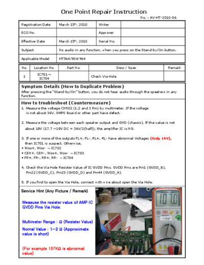
Image preview - the first page of the document

>> Download HT904TABHUNLL_SI_1376305095 documenatation <<
Text preview - extract from the document
                          One Point Repair Instruction
                                                                           No. : AV-HT-2010-06

Registration Date        March 15th, 2010       Writer

ECO No.                                         Approver

Effective Date           March 15th, 2010       Serial No.

Subject                  No audio in any function, when you press on the Stand-by/On button.

Applicable Model         HT564/904/964

No.       Location No.       Part No.                        Desc / Spec                 Remark
           IC701 ~
 1                                          Check Via Hole
            IC704

Symptom Details (How to Duplicate Problem)
After pressing the "Stand-by/On" button, you do not hear audio through the speakers in any
function.

How to troubleshoot (Countermeasure)
1. Measure the voltage CN902 (1,2 and 3 Pin) by multimeter. If the voltage
   is not about 36V, SMPS Board or other part have defect.

2. Measure the voltage between each speaker output and GND (chassis). If the value is not
  about 18V (17.7 ~18V DC = 36V/2(half)), the amplifier IC is NG.

3. If one or more of the outputs FL+, FL-, RL+, RL- have abnormal Voltages (Only 10V),
  then IC701 is suspect. Otherwise,
 Woo+, Woo-  IC702
 CEN+, CEN-, Woo+, Woo-  IC703
 FR+, FR-, RR+, RR-  IC704

4. Check the Via Hole Resister Value of IC GVDD Pins. GVDD Pins are Pin1 (GVDD_B),
   Pin22 (GVDD_C), Pin23 (GVDD_D) and Pin44 (GVDD_A).

5. If you find to open the Via Hole, connect with wire about open the Via Hole.

Service Hint (Any Picture / Remark)

Measuse the resister value of AMP IC
GVDD Pins Via Hole.


Multimeter Range :  (Resister Value)
Nornal Value : 1~2  (Approximate
value is short)


(For example 107K is abnormal
value)
                  One Point Repair Instruction
                                                        No. : AV-HT-2010-06

TI AMP IC701 ~ 704 (GVDD Pin Check Point)


  Check the Via Hole Resister Value of IC GVDD Pins.
   GVDD Pins are Pin1 (GVDD_B), Pin22 (GVDD_C), Pin23 (GVDD_D)
    and Pin44 (GVDD_A).
                  One Point Repair Instruction
                                                    No. : AV-HT-2010-06

TI AMP IC701 (GVDD Pin Check Point) (FL+, FL-, RL+, RL-)


                 Soldering Point


    PIN 44                                                     PIN 23


     Connect by wire

     PIN 1                                                      PIN 22


                                        PIN 23


  PIN 44


                                                      PIN 22


                 PIN 1
                One Point Repair Instruction
                                                   No. : AV-HT-2010-06

TI AMP IC702 (GVDD Pin Check Point) (W+, W-)


                                                            PIN 23

                                                     Soldering Point


                                 Connect by wire
                                                           PIN 22


                                                               PIN 23


                                                           PIN 22
                  One Point Repair Instruction
                                                  No. : AV-HT-2010-06

TI AMP IC703 (GVDD Pin Check Point) (W+, W-, C+, C-)


 PIN 44


Soldering Point                                             PIN 23


                          Connect by wire

     PIN 1                                                 PIN 22


                                                       PIN 23

 PIN 44


                  PIN 1
                                                       PIN 22
                  One Point Repair Instruction
                                                   No. : AV-HT-2010-06

TI AMP IC704 (GVDD Pin Check Point) (FR+, FR-, RR+, RR-)


         PIN 44                                             PIN 23


           Connect by wire
         PIN 1                                           PIN 22


       PIN 44

                                                           PIN 23


                  PIN 1


                                                PIN 22
◦ Jabse Service Manual Search 2024 ◦ Jabse Pravopis ◦ onTap.bg ◦ Other service manual resources online : Fixya ◦ eServiceinfo