Service Manuals, User Guides, Schematic Diagrams or docs for : LG Car Audio tcc-733 TCC-77~1
<< Back | HomeMost service manuals and schematics are PDF files, so You will need Adobre Acrobat Reader to view : Acrobat Download Some of the files are DjVu format. Readers and resources available here : DjVu Resources
For the compressed files, most common are zip and rar. Please, extract files with Your favorite compression software ( WinZip, WinRAR ... ) before viewing. If a document has multiple parts, You should download all, before extracting.
Good luck. Repair on Your own risk. Make sure You know what You are doing.
Image preview - the first page of the document
>> Download TCC-77~1 documenatation <<
Text preview - extract from the document
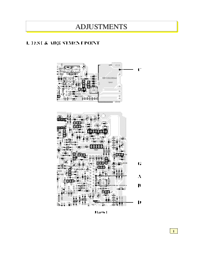
                 ADJUSTMENTS

1. TEST & ADJUSTMENT POINT


                                    C


                                    G

                                    A
                                    B


                                    D
                        Figure 1.


                                        1
2. FM ADJUSTMENT


                                                                         Figure 2.

(1) The impedance of FM antenna terminal is 75.
    Therefore, connect coaxial cable (3C-2V etc.) between FM SG and antenna terminal when wiring.
                       Item         FM SSG                Available              Antenna
                                   Attenuator               Power               Terminal
        Type                       Indication                Rato                 Voltage
        Open indication                 0dB                 5.2dBf                6dB/uV
        type                           60dB                65.2dBf               66dB/uV
        Load or close                   0dB                11.2dBf               12dB/uV
        indication type                54dB                65.2dBf               66dB/uV

(2) There are two kind in indication of FM SG output attenuator
   1) Attenuator with marking of 75 open ... open indication type.
   2) Attenuator with marking of 75 load or close ... load or close indication type.

(3) FM SG output level in this FM adjustment are described as open indication type. The left table shows
    relations among FM SG attenuator indication (dB), available power ratio (dBf) and antenna terminal voltage
   (dB/uV) in each indication type.

NOTE: 1. BAND Switch .................................................................................................................................. FM
      2. BALANCE .................................................................................................................................... Center
      3. TREB/BASS .................................................................................................................................. Center
      4. Connect as shown in figure 2.
      5. Refer to figure 1 for Adjustmenu Points.
                                     FEED SIGNAL
 STEP          SUBJECT                                            MEASURE OUTPUT                  ADJUSTMENT              ADJUST FOR         REMARK
                                  FROM               TO
                              98MHz 60dB ANT Jack
                                                               Between Point A & Point
    1     Discriminator       No Dev.           or                                                       T101            DC 0V
◦ Jabse Service Manual Search 2024 ◦ Jabse Pravopis ◦ onTap.bg ◦ Other service manual resources online : Fixya ◦ eServiceinfo