Service Manuals, User Guides, Schematic Diagrams or docs for : Pioneer Car Audio deh-p6000r_deh-p7000r_196
<< Back | HomeMost service manuals and schematics are PDF files, so You will need Adobre Acrobat Reader to view : Acrobat Download Some of the files are DjVu format. Readers and resources available here : DjVu Resources
For the compressed files, most common are zip and rar. Please, extract files with Your favorite compression software ( WinZip, WinRAR ... ) before viewing. If a document has multiple parts, You should download all, before extracting.
Good luck. Repair on Your own risk. Make sure You know what You are doing.
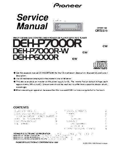
Image preview - the first page of the document

>> Download deh-p6000r_deh-p7000r_196 documenatation <<
Text preview - extract from the document
      Service                                                       DEH-P7000R/EW


      Manual                                                                                                                                 ORDER NO.
                                                                                                                                         CRT2375

MULTI-CD/MD/DAB CONTROL HIGH POWER CD PLAYER WITH RDS TUNER


DEH-P7000R                                                                                                                                             EW

DEH-P7000R-W                                                                                                     EW

DEH-P6000R                                                                                   EW


- See the separate manual CX-916(CRT2300) for the CD mechanism description, disassembly and circuit
      description.
- The CD mechanism employed in this model is one of S8 series.
- This device employs an inverter as the power supply for EL. The inverter has an output voltage reach
      approximately 500 volts(AC). Utmost care should be used not to suffer from a possible electric shock,
      accordingly.
- When executing an operation, be aware that the in around IC651 can become quite hot to the touch.


CONTENTS
 1.   SAFETY INFORMATION ............................................2         7. GENERAL INFORMATION .......................................68
 2.   EXPLODED VIEWS AND PARTS LIST .......................3                      7.1 PARTS .................................................................68
 3.   BLOCK DIAGRAM AND SCHEMATIC DIAGRAM ...14                                       7.1.1 IC................................................................68
 4.   PCB CONNECTION DIAGRAM ................................40                       7.1.2 DISPLAY ....................................................76
 5.   ELECTRICAL PARTS LIST ........................................50            7.2 DIAGNOSIS ........................................................77
 6.   ADJUSTMENT..........................................................64          7.2.1 DISASSEMBLY .........................................77
                                                                                      7.2.2 TEST MODE ..............................................82
                                                                               8. OPERATIONS AND SPECIFICATIONS.....................86


PIONEER ELECTRONIC CORPORATION                   4-1, Meguro 1-Chome, Meguro-ku, Tokyo 153-8654, Japan
PIONEER ELECTRONICS SERVICE INC. P.O.Box 1760, Long Beach, CA 90801-1760 U.S.A.
PIONEER ELECTRONIC [EUROPE] N.V. Haven 1087 Keetberglaan 1, 9120 Melsele, Belgium
PIONEER ELECTRONICS ASIACENTRE PTE.LTD. 253 Alexandra Road, #04-01, Singapore 159936

C PIONEER ELECTRONIC CORPORATION 1999                                                                             K-ZZD. FEB. 1999 Printed in Japan
DEH-P7000R,P7000R-W,P6000R


- CD Player Service Precautions
1. For pickup unit(CXX1285) handling, please refer             2. During disassembly, be sure to turn the power off
   to"Disassembly"(see page 77).                                  since an internal IC might be destroyed when a con-
   During replacement, handling precautions shall be              nector is plugged or unplugged.
   taken to prevent an electrostatic discharge(protection      3. Please checking the grating after changing the ser-
   by a short pin).                                               vice pickup unit(see page 66).


1. SAFETY INFORMATION
This service manual is intended for qualified service technicians; it is not meant for the casual do-it-yourselfer.
Qualified technicians have the necessary test equipment and tools, and have been trained to properly and safely repair
complex products such as those covered by this manual.
Improperly performed repairs can adversely affect the safety and reliability of the product and may void the warranty.
If you are not qualified to perform the repair of this product properly and safely; you should not risk trying to do so
and refer the repair to a qualified service technician.

1. Safety Precautions for those who Service this Unit.
◦ Jabse Service Manual Search 2024 ◦ Jabse Pravopis ◦ onTap.bg ◦ Other service manual resources online : Fixya ◦ eServiceinfo