Service Manuals, User Guides, Schematic Diagrams or docs for : Pioneer Audio htz-7_205
<< Back | HomeMost service manuals and schematics are PDF files, so You will need Adobre Acrobat Reader to view : Acrobat Download Some of the files are DjVu format. Readers and resources available here : DjVu Resources
For the compressed files, most common are zip and rar. Please, extract files with Your favorite compression software ( WinZip, WinRAR ... ) before viewing. If a document has multiple parts, You should download all, before extracting.
Good luck. Repair on Your own risk. Make sure You know what You are doing.
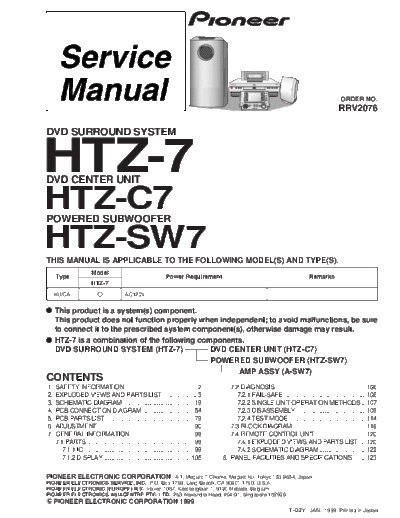
Image preview - the first page of the document

>> Download htz-7_205 documenatation <<
Text preview - extract from the document
                                                                                                                                       ORDER NO.
                                                                                                                                      RRV2076

DVD SURROUND SYSTEM


HTZ-7
DVD CENTER UNIT

HTZ-C7
POWERED SUBWOOFER

HTZ-SW7
THIS MANUAL IS APPLICABLE TO THE FOLLOWING MODEL(S) AND TYPE(S).
                       Model
     Type                                                   Power Requirement                                            Remarks
                       HTZ-7
     KU/CA                              AC120V


     This product is a system(s) component.
     This product does not function properly when independent; to avoid malfunctions, be sure
     to connect it to the prescribed system component(s), otherwise damage may result.
     HTZ-7 is a combination of the following components.
     DVD SURROUND SYSTEM (HTZ-7)                DVD CENTER UNIT (HTZ-C7)
                                                POWERED SUBWOOFER (HTZ-SW7)
                                                       AMP ASSY (A-SW7)
CONTENTS
1.   SAFETY INFORMATION ....................................... 2                    7.2 DIAGNOSIS ................................................. 106
2.   EXPLODED VIEWS AND PARTS LIST ................... 3                               7.2.1 FAIL-SAFE ............................................ 106
3.   SCHEMATIC DIAGRAM ...................................... 19                       7.2.2 SINGLE UNIT OPERATION METHODS .. 107
4.   PCB CONNECTION DIAGRAM ............................ 54                            7.2.3 DISASSEMBLY ..................................... 109
5.   PCB PARTS LIST ................................................ 79                7.2.4 TEST MODE ......................................... 114
6.   ADJUSTMENT .................................................... 90              7.3 BLOCK DIAGRAM ....................................... 118
7.   GENERAL INFORMATION .................................. 99                       7.4 REMOTE CONTROL UNIT ........................... 120
     7.1 PARTS .......................................................... 99           7.4.1 EXPLODED VIEWS AND PARTS LIST ... 120
       7.1.1 IC ............................................................ 99        7.4.2 SCHEMATIC DIAGRAM ......................... 122
       7.1.2 DISPLAY ............................................... 105          8. PANEL FACILITIES AND SPECIFICATIONS ...... 123

PIONEER ELECTRONIC CORPORATION              4-1, Meguro 1-Chome, Meguro-ku, Tokyo 153-8654, Japan
PIONEER ELECTRONICS SERVICE, INC. P.O. Box 1760, Long Beach, CA 90801-1760, U.S.A.
PIONEER ELECTRONIC (EUROPE) N.V. Haven 1087, Keetberglaan 1, 9120 Melsele, Belgium
PIONEER ELECTRONICS ASIACENTRE PTE. LTD. 253 Alexandra Road, #04-01, Singapore 159936
     PIONEER ELECTRONIC CORPORATION 1999
                                                                                                               T
◦ Jabse Service Manual Search 2024 ◦ Jabse Pravopis ◦ onTap.bg ◦ Other service manual resources online : Fixya ◦ eServiceinfo