Service Manuals, User Guides, Schematic Diagrams or docs for : Stanford Research Systems www.thinksrs.com-LDC Note 8 Modulation Behavior
<< Back | HomeMost service manuals and schematics are PDF files, so You will need Adobre Acrobat Reader to view : Acrobat Download Some of the files are DjVu format. Readers and resources available here : DjVu Resources
For the compressed files, most common are zip and rar. Please, extract files with Your favorite compression software ( WinZip, WinRAR ... ) before viewing. If a document has multiple parts, You should download all, before extracting.
Good luck. Repair on Your own risk. Make sure You know what You are doing.
Image preview - the first page of the document

>> Download www.thinksrs.com-LDC Note 8 Modulation Behavior documenatation <<
Text preview - extract from the document
LDC501 Current Source Response to Modulation Signals
                                                                                                         Rev B. Revised Oct 2012


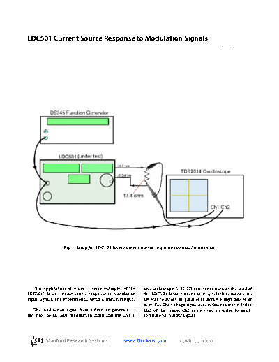
                    Fig.1  Setup for LDC501 laser current source response to modulation input


   This  application  note  shows  some  examples  of  the      an oscilloscope. A 17.4 resistor is used as the load of
LDC501's laser current source response to modulation            the  LDC501  laser  current  source,  which  is  made  with
input signals. The experimental setup is shown in Fig.1.        several  resistors  in  parallel  to  achieve  high  power  of
                                                                over 4W. The voltage signal across this resistor is fed to
   The  modulation  signal  from  a function generator  is      Ch2  of  the  scope.  Ch2  is  inverted  in  order  to  easily
fed  into  the  LDC501  modulation  input  and  the  Ch1  of    compare with input signal.


                 Stanford Research Systems               www.thinksrs.com            (408)7449040                         -1-
1. Sine and Triangle wave response

    In Fig.2 the LDC501 output current setpoint is 250mA. The blue trace is the input signal which is 100kHz and
6Vpp. The red trace is the output voltage across 17.4. The vertical axis is 0.87V/div which corresponds to
50mA/div (=0.87/17.4).


                         Fig.2  LDC501's response to 100kHz Sine wave and triangle wave


2. Square wave and step response

    In Fig.3 the blue trace is the input square wave which is 100kHz and 6Vpp. The red trace is the output voltage
across 17.4. The vertical axis is 0.87V/div which corresponds to 50mA/div. The rising edge is about 0.3us
corresponding to 0.35/0.3 = 1.17MHz bandwidth.


                        Fig.3  LDC501 response to 100kHz square wave and step response


                 Stanford Research Systems               www.thinksrs.com            (408)7449040               -2-

3. Limited output

    In Fig.4 the output current setpoint is 250mA and current limit setting is 300mA. The blue trace is the
modulation input signal whose amplitude is 6Vpp with 10kHz, 50kHz, 100kHz or 500kHz frequencies. The red
traces are the output voltages across the 17.4 resistor load.

    The overshoot is dependent on the cable parasitic parameters and the slew rate of the input signal.


                                 Fig.4  LDC501 limits the output current to 300mA.


                 Stanford Research Systems               www.thinksrs.com            (408)7449040              -3-
4. Recovery from 0mA

   In Fig.5 the output current will not go below 0mA. When modulation pushes output to go to 0mA, a short
recovery time is required to allow the internal current source to get out of saturation.


                                      Fig.5  LDC501 recovers from 0mA output.


5. Bandwidth change

   A smooth transition will occur during bandwidth changes. In Fig.6, a bandwidth change will not cause output
current glitches.


                        Fig.6  LDC501 bandwidth change from 1.2MHz to 10kHz and back.


                 Stanford Research Systems               www.thinksrs.com            (408)7449040              -4-
6. Mode change

    CC to CP, or CP to CC mode changes can be done while the laser is on. A smooth transition will occur without
glitches  in  the  output  current.  In  Fig.7  the  input  modulation  signal  is  5kHz.  In  CC  mode,  the  LDC501  has  a
bandwidth of 1.2MHz whereas CP mode has lower bandwidth of 5kHz and also has a different transfer functions.


                                      Fig.7  CC to CP,  and CP to CC mode changes.


7. Soft start and turnoff of the current source

    When LDC501 is turned ON, the output current will softly rise to its setting point (250mA in Fig.8 and is
modulated). When it's turned OFF, the output current will shut off  immediately.


                        Fig.8  LDC501 soft start with modulation input and the fast turnoff.


                 Stanford Research Systems               www.thinksrs.com            (408)7449040                       -5-
◦ Jabse Service Manual Search 2024 ◦ Jabse Pravopis ◦ onTap.bg ◦ Other service manual resources online : Fixya ◦ eServiceinfo