Service Manuals, User Guides, Schematic Diagrams or docs for : Samsung Audio MAX-DJ750 20050617095258859_DJ750_2Trouble_TM

<< Back | Home

Most service manuals and schematics are PDF files, so You will need Adobre Acrobat Reader to view : Acrobat Download Some of the files are DjVu format. Readers and resources available here : DjVu Resources
For the compressed files, most common are zip and rar. Please, extract files with Your favorite compression software ( WinZip, WinRAR ... ) before viewing. If a document has multiple parts, You should download all, before extracting.
Good luck. Repair on Your own risk. Make sure You know what You are doing.


Image preview - the first page of the document
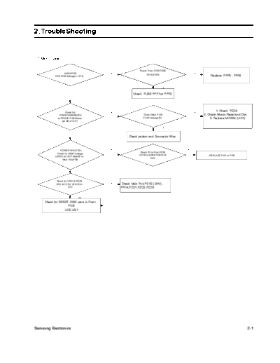
20050617095258859_DJ750_2Trouble_TM


>> Download 20050617095258859_DJ750_2Trouble_TM documenatation <<

Text preview - extract from the document
2. TroubleShooting


 1.Main(Power)


                                                             Power Trans PCB FUSE
                  MAIN PCB                 NO                                                NO
                                                                  PPF5,PPF6                           Replace PPF5 , PPF6
            PC5,PCB Voltage(+/- 21V)


                                                                              YES

                               YES                      Check FUSE PPF1,or PPF2


                     Check for
                                                                                                          1. Check PZD4.
                                           NO                                                NO
               POWER-SENSE(5V)                                 Check Main PCB                     2. Check Micom Reset and Osc .
              at FRONT PCB Micom                               PC42 Voltage 5V.                       3. Replace MICOM (UIC1)
                  pin #9 of UIC1

                                                                              YES


                               YES
                                                     Check pattern and Connector Wire


                 POWER ON LEVEL            NO                                           NO
                                                             Check 5V in Front PCB
              Check for HIGH Voltage
                                                            UC16 or MAIN PCB PIC4                    REPLACE PIC4 or PR5
            (>3.5V) at UIC1; #pin82 or
                                                                     5.6V
                  Main Pcb PR9


                               YES


            Check for VFD1,2-53,54
                                           NO    Check Main Pcb PC10 (-34V) ,
            VFD AC 3.5V, VFD PIN :-
                       27V                      PR14,PZD1,PZD2,PZD3


                               YES

     Check for RESET /OSC parts in Front
                     PCB
                  :UX2,UQ1


Samsung Electronics                                                                                                            2-1
      2.Output


                                       YES
                  Protection WORK                PROTECTION Troubleshooting


                              NO


                    DVD PACK          NO
                                              DVD PACK WORKING Troubleshooting
                   WORKING OK


                             YES


               Check Signal at         NO           Check Signal in DVD            NO
             Connector ACW2 l on                    POWER PCB                           FIC1 INPUT and OUTPUT CHECK
                  AMP PCB                           FIC4,FIC2,FIC80


                             YES                        PARTS OPEN/SHORT


                   Check Mute on
                  Connector ACW2       HIGH
                 #PIN 2, PIN3, PIN4                    MICOM UIC1 :99#PIN
                 (H:Mute:L: Normal)             and MAIN PCB MIC1 : #PIN12 CHECK


                             LOW


                    Check             NO        MUTE Transtor Circuit Check.
               AIC1,AIC3,AIC21
                                                    AQ30~36,54~56.
             #PIN 10,PIN15 Signal


                          YES


             When POWER OFF ,
              Check MOSFET                    Replace AFQ1~8,21~24 No Good
              AFQ1~8,21~24                               MOSFET
             DS,GS,DS Voltage


                 Replace AIC1,3,21


2-2                                                                                                      Samsung Electronics
          3.Protection


                                                    NO         OUTPUT LEVEL HIGH PROTECTION.
                     Power On Protection                      1.Please Refer Output troubleshooting
                                                                 2. Speaker terminal short check


                                   YES


                      When Power Off,              NO                     1. Replace Not Good MOSFET
                      Check MOSFET                                    2. Check and Replace AZD1~8,21~28
                      AFQ1~8,21~24                               3. Check and Replace AR40,80,45,95,240,245


                                   YES


              After OPEN Protection sensor port:
                 MAIN PCB JW172 (JUMPER),
                  CHECK PROTECTION PORT


                                                                MICOM PORT 3#
                                                    YES                                       HIGH
                                                                CHECK .
                        Protection ?                                                                     Replace MICOM IC UIC1
                                                                LOW: protection
                                                                High : Normal


                                   NO                                           LOW


                                                          PROTECTION PATTERN LINE
                                                                  CHECK


                    AMP PCB +34V/-34V               NO
                                                            1. +5V/-5V Check DVD POWER PCB FQ5,DPIC4
                    and +5V/-5V CHECK
                                                             2. +/-34V Check Power Trans PCB RELAY1,2


                                   YES


                  Replace AMP PCB AIC1,3,21


Samsung Electronics                                                                                                              2-3
      4.DVD PACK


                                              YES   DVD PACK Signal Voltage +/- 8V Check :DVD
                  PLAYING OK
                                                    POWER PCB : CONNECTOR DPCW1 #PIN7,8


                           NO


                    DVD PACK              YES        1. FRONT PCB to DVD PACK 18PIN CABLE
               5V,3.3V,8V(MOTOR)                                     CHECK
                     CHECK                                   2. MICOM UIC1 CHECK


             1. DVD POWER DPIC1,2,3 CHECK
         2. DVD POWER ON CONTROL PORT Level
       Check: CONNECTOR PORT FCW6 #PIN1 and
                   MICOM UIC1 #PIN 95.


2-4                                                                                        Samsung Electronics


◦ Jabse Service Manual Search 2024 ◦ Jabse PravopisonTap.bg ◦ Other service manual resources online : FixyaeServiceinfo