Service Manuals, User Guides, Schematic Diagrams or docs for : Samsung DVD DVD-D530 DVDD530_ET-SB-EX-SI_1346063369
<< Back | HomeMost service manuals and schematics are PDF files, so You will need Adobre Acrobat Reader to view : Acrobat Download Some of the files are DjVu format. Readers and resources available here : DjVu Resources
For the compressed files, most common are zip and rar. Please, extract files with Your favorite compression software ( WinZip, WinRAR ... ) before viewing. If a document has multiple parts, You should download all, before extracting.
Good luck. Repair on Your own risk. Make sure You know what You are doing.
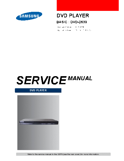
Image preview - the first page of the document

>> Download DVDD530_ET-SB-EX-SI_1346063369 documenatation <<
Text preview - extract from the document
                                  DVD PLAYER
                                  BASIC : DVD-D530
                                   Application Model :   DVD-D530
                                   Application Area :    ZF, XN, XE, EN, ZV, XU


SERVICE                                        MANUAL
   DVD PLAYER


 Refer to the service manual in the GSPN (see the rear cover) for more information.
                                                                                                               1. Precautions


1. Precautions

1.1. Safety Precautions

1) Before returning an instrument to the customer, always make a safety check of the entire instrument, including, but not
   limited to, the following items:
    a) Be sure that no built-in protective devices are defective or have been defeated during servicing
         i) Protective shields are provided to protect both the technician and the customer. Correctly replace all missing
            protective shields, including any removed for servicing convenience.
         ii) When reinstalling the chassis and/or other assembly in the cabinet, be sure to put back in place all protective
             devices, including, but not limited to, nonmetallic control knobs, insulating fish papers, adjustment and
             compartment covers/shields, and isolation resistor/capacitor networks. Do not operate this instrument or permit
             it to be operated without all protective devices correctly installed and functioning.
    b) Be sure that there are no cabinet openings through which adults or children might be able to insert their fingers and
       contact a hazardous voltage. Such openings include, but are not limited to, excessively wide cabinet ventilation
       slots, and an improperly fitted and/or incorrectly secured cabinet back cover.
    c) Leakage Current Hot Check -- With the instrument completely reassembled, plug the AC line cord directly into a
       230V(220V ~ 240V) AC outlet. (Do not use an isolation transformer during this test.)
        Use a leakage current tester or a metering system that complies with American National Standard Institute (ANSI)
        C101.1 Leakage Current for Appliances and Underwriters Laboratories (UL) 1270 (40.7). With the instrument's
        AC switch first in the ON position and then in the OFF position, measure from a known earth ground (metal
        water pipe, conduit, etc.) to all exposed metal parts of the instrument (antennas, handle brackets, metal cabinets,
        screwheads, metallic overlays, control shafts, etc.), especially any exposed metal parts that offer an electrical
        return path to the chassis.
        Any current measured must not exceed 0.5mA.
        Reverse the instrument power cord plug in the outlet and repeat the test. See
        Any measurements not within the limits specified herein indicate a potential shock hazard that must be eliminated
        before returning the instrument to the customer.


                                                      Fig. 1-1 AC Leakage Test


    d) Insulation Resistance Test Cold Check -- (1) Unplug the power supply cord and connect a jumper wire between
       the two prongs of the plug. (2) Turn on the power switch of the instrument. (3) Measure the resistance with
       an ohmmeter between the jumpered AC plug and all exposed metallic cabinet parts on the instrument, such as
       screwheads, antenna, control shafts, handle brackets, etc. When an exposed metallic part has a return path to the
       chassis, the reading should be between 1 and 5.2 megohm. When there is no return path to the chassis, the reading
       must be infinite. If the reading is not within the limits specified, there is the possibility of a shock hazard, and the
       instrument must be repaired and rechecked before it is returned to the customer. See


Copyright
◦ Jabse Service Manual Search 2024 ◦ Jabse Pravopis ◦ onTap.bg ◦ Other service manual resources online : Fixya ◦ eServiceinfo