Service Manuals, User Guides, Schematic Diagrams or docs for : Samsung Dishwashers DMT400RHS Service Manuals SM_DMT800_610_5F400_350_7933_DW80F800_600_v05_20130515

<< Back | Home

Most service manuals and schematics are PDF files, so You will need Adobre Acrobat Reader to view : Acrobat Download Some of the files are DjVu format. Readers and resources available here : DjVu Resources
For the compressed files, most common are zip and rar. Please, extract files with Your favorite compression software ( WinZip, WinRAR ... ) before viewing. If a document has multiple parts, You should download all, before extracting.
Good luck. Repair on Your own risk. Make sure You know what You are doing.


Image preview - the first page of the document
SM_DMT800_610_5F400_350_7933_DW80F800_600_v05_20130515


>> Download SM_DMT800_610_5F400_350_7933_DW80F800_600_v05_20130515 documenatation <<

Text preview - extract from the document
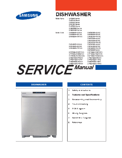
              DISHWASHER
              Model Name   : DMT800 Series
                             DMT610 Series
                             DMT400 Series
                             DMT350 Series
                             DW7933 Series
                             DW80F800 Series
                             DW80F600 Series
              Model Code   : DMT800RHS/XAA      DMT800RHS/XAC
                             DMT800RHB/XAA      DMT800RHB/XAC
                             DMT800RHW/XAA      DMT800RHW/XAC
                                                DMT610RHS/XAC
                                                DMT610RHB/XAC
                                                DMT610RHW/XAC
                             DMT400RHS/XAA      DMT400RHS/XAC
                             DMT400RHB/XAA      DMT400RHB/XAC
                             DMT400RHW/XAA      DMT400RHW/XAC
                                                DMT350RFS/XAC
                             DW7933LRASR/XAA    DW7933LRASR/XAC
                             DW7933LRABB/XAA    DW7933LRABB/XAC
                             DW7933LRAWW/XAA    DW7933LRAWW/XAC
                             DW80F800UWS/AA     DW80F800UWS/AC
                             DW80F600UTS/AA     DW80F600UTS/AC
                             DW80F600UTB/AA     DW80F600UTB/AC


SERVICE
                             DW80F600UTW/AA     DW80F600UTW/AC

                                   Manual

 DISHWASHER                              CONTENTS

                            1. Safety Instructions

                            2.

                            3. Disassembly and Reassembly

                            4. Troubleshooting

                            5. PCB Diagram

                            6. Wiring Diagram

                            7. Schematic Diagram

                            8. Reference
CONTENTS
1. Safety Instructions . . . . . . . . . . . . . . . . . . . . . . . . . . . . . . . . . . . . . . . . . . . . . . . . . . . . . . . . . . . . . . . . . . . 1
   1-1. Safety Instructions for Service Engineers . . . . . . . . . . . . . . . . . . . . . . . . . . . . . . . . . . . . . . . . . . . . . 1

                                               . . . . . . . . . . . . . . . . . . . . . . . . . . . . . . . . . . . . . . . . . . . . . . . . . . . . . . . . . . .5
    2-1.      Features . . . . . . . . . . . . . . . . . . . . . . . . . . . . . . . . . . . . . . . . . . . . . . . . . . . . . . . . . . . . . . . . . . . . . . .5
                               . . . . . . . . . . . . . . . . . . . . . . . . . . . . . . . . . . . . . . . . . . . . . . . . . . . . . . . . . . . . . . . . . . .6
                                                                                   . . . . . . . . . . . . . . . . . . . . . . . . . . . . . . . . . . . . . . . . .7
                                             . . . . . . . . . . . . . . . . . . . . . . . . . . . . . . . . . . . . . . . . . . . . . . . . . . . . . . . . . . . .9

3. Disassembly and Reassembly . . . . . . . . . . . . . . . . . . . . . . . . . . . . . . . . . . . . . . . . . . . . . . . . . . . . . . . . . 10
                                              . . . . . . . . . . . . . . . . . . . . . . . . . . . . . . . . . . . . . . . . . . . . . . . . . 10
                                          . . . . . . . . . . . . . . . . . . . . . . . . . . . . . . . . . . . . . . . . . . . . . . . . . . . 11
                                                  . . . . . . . . . . . . . . . . . . . . . . . . . . . . . . . . . . . . . . . . . . . . . . . 37

4. Troubleshooting . . . . . . . . . . . . . . . . . . . . . . . . . . . . . . . . . . . . . . . . . . . . . . . . . . . . . . . . . . . . . . . . . . . . 38
                             . . . . . . . . . . . . . . . . . . . . . . . . . . . . . . . . . . . . . . . . . . . . . . . . . . . . . . . . . . . . . . . 38
                                         . . . . . . . . . . . . . . . . . . . . . . . . . . . . . . . . . . . . . . . . . . . . . . . . . . . . . . . . . 43
                                         . . . . . . . . . . . . . . . . . . . . . . . . . . . . . . . . . . . . . . . . . . . . . . . . . . . . . . . . . 45
                                         . . . . . . . . . . . . . . . . . . . . . . . . . . . . . . . . . . . . . . . . . . . . . . . . . . . . . . . . . 47

5. Pcb Diagram . . . . . . . . . . . . . . . . . . . . . . . . . . . . . . . . . . . . . . . . . . . . . . . . . . . . . . . . . . . . . . . . . . . . . . .63
                   . . . . . . . . . . . . . . . . . . . . . . . . . . . . . . . . . . . . . . . . . . . . . . . . . . . . . . . . . . . . . . . . . . . . . 63
                   . . . . . . . . . . . . . . . . . . . . . . . . . . . . . . . . . . . . . . . . . . . . . . . . . . . . . . . . . . . . . . . . . . . . . 64

6. Wiring Diagram . . . . . . . . . . . . . . . . . . . . . . . . . . . . . . . . . . . . . . . . . . . . . . . . . . . . . . . . . . . . . . . . . . . . . 65
                                                                        . . . . . . . . . . . . . . . . . . . . . . . . . . . . . . . . . . . . . . . . . . 65
                                                  . . . . . . . . . . . . . . . . . . . . . . . . . . . . . . . . . . . . . . . . . . . . . . . . . . . . . 66
                                                                              . . . . . . . . . . . . . . . . . . . . . . . . . . . . . . . . . . . . . . . 67

7. Schematic Diagram . . . . . . . . . . . . . . . . . . . . . . . . . . . . . . . . . . . . . . . . . . . . . . . . . . . . . . . . . . . . . . . . . 68
                   . . . . . . . . . . . . . . . . . . . . . . . . . . . . . . . . . . . . . . . . . . . . . . . . . . . . . . . . . . . . . . . . . . . 68

8. Reference . . . . . . . . . . . . . . . . . . . . . . . . . . . . . . . . . . . . . . . . . . . . . . . . . . . . . . . . . . . . . . . . . . . . . . . . . 69
                                                     . . . . . . . . . . . . . . . . . . . . . . . . . . . . . . . . . . . . . . . . . . . . . . . . . . . . . 69
                                                     . . . . . . . . . . . . . . . . . . . . . . . . . . . . . . . . . . . . . . . . . . . . . . . . . . . . . 70
                                                     . . . . . . . . . . . . . . . . . . . . . . . . . . . . . . . . . . . . . . . . . . . . . . . . . . . . . 71
                           . . . . . . . . . . . . . . . . . . . . . . . . . . . . . . . . . . . . . . . . . . . . . . . . . . . . . . . . . . . . . . . . . . 72
1. SAFETY INSTRUCTIONS

1-1. SAFETY INSTRUCTIONS FOR SERVICE ENGINEERS


         Warning

         Caution


   Warning

                           Before Servicing


  same time.


                                                 Safety Instructions _ 1
                          While Servicing


   parts.


                          After Servicing


2 _ Safety Instructions
Caution

                       Before Servicing


                       During Servicing


   moisture from it.


                                          Safety Instructions _ 3
                          After Servicing


4 _ Safety Instructions
2. FEATURES AND SPECIFICATIONS

2-1. FEATURES
        Features                     Description   Remarks


                    performance.


                    easier to use.
2-2. SPECIFICATIONS


Type


                                                                        Vapor vent cover


                  Above images might differ in the dishwasher models.
2-3. COMPARING SPECIFICATIONS WITH EXISTING MODELS

                                        NEW MODEL                         BASIC MODEL
          Model
                                       DW80F800UWS                     DW7933LRASR/BB/WW


          Photo


      Panel Control                          Black

       Control Type                         Touch
       Frame Front                           STS
      Basket Handle                       Gray + STS                           X


  Soil Detection Sensors                       O                               O
      Drying method                Air diffusion condensing
 Basket Height Adjustment                 One-touch                          2-stage

     Leakage Sensor                            O                               O


                                              6
                                                                               4
        Programs             (Normal, Heavy, Delicate, Pot&Pans,
                                    Quick+, Smart Auto)


                                                6
                                                                               3
         Options            (Delay Start, Sanitize, Half Load, Storm
                                Wash, Child Lock, Start/Drain)
                               NEW MODEL                 BASIC MODEL
         Model
                            DW80F600UTS/B/W           DW7933LRASR/BB/WW


         Photo


     Panel Control                  Black

      Control Type                  Touch
      Frame Front
     Basket Handle                  Gray                      X


 Soil Detection Sensors               O                       O
     Drying method         Air diffusion condensing
Basket Height Adjustment           2-stage                  2-stage

    Leakage Sensor                    O                       O


                                      4                       4
       Programs


                                      3                       3
        Options
2-4. OPTIONS SPECIFICATIONS

               Photo          Item      Code   QTY   Remarks


                                                2


                                                1


   For top mount


                          Leg support           2


                                                1


                                                1


                                         -      1


                                         -      1


                                         -      1


                                         -      1


                                         -      1


                                         -      1
3. DISASSEMBLY AND REASSEMBLY

3-1. TOOLS FOR REMOVAL AND REASSEMBLY


     No.                              Type
      
                                             Leg


                                      10mm


* Preparation for parts replacement


10 _ Disassembly and Reassembly
3-2. STANDARD DISASSEMBLY DRAWINGS

   Warning
Always disconnect the electric power supply & water supply before servicing


   Caution


       Part                          Photo                                    Description


- Fasten type
                       Fasten type                 P-Lock type      P-Lock type             Fasten type


                         Buckle


- Fasten type


                                                                        Disassembly and Reassembly _ 11
       Part                       Figure                  Description

                                           Preparation:


     Main PBA


12 _ Disassembly and Reassembly
      Part         Figure                  Description
                            Preparation:


  Frame front                  Caution


                            Preparation


Door Lock Switch
  (Door latch)


                                  Disassembly and Reassembly _ 13
      Part                  Figure                  Description


                                     Preparation:


  Control Panel
       +
  Window Panel
    (DMT800)


                                     Preparation:


  Control Panel
   (DMT610)


14 _ Disassembly and Reassembly
    Part        Figure                      Description


                         Preparation:


Control Panel
 (DMT400)


                         Preparation:


Control Panel
 (DMT350)


                                        Disassembly and Reassembly _ 15
      Part                  Figure   Description


  Control Panel
   (DW7933)


16 _ Disassembly and Reassembly
    Part        Figure                      Description
                         Preparation:


Control Panel
(DW80F800 ,
 DW80F600)


                                        Disassembly and Reassembly _ 17
        Part                      Figure                   Description

                                           Air Diffusion Condensing Dry system


                                           Preparation:


Condensing dry system
 (DMT800/610/400/350,
DW80F800, DW80F600)


                                              vent.


18 _ Disassembly and Reassembly
        Part           Figure                 Description


  Condensing dry
     system

  Assy Case Vent
         &
   Assy Dry Duct
         &
Assy Duct Condenser
(DMT800/610/400/350,
    DW80F800,
    DW80F600)
                                Caution


  Assy Case Vent
(DMT800/610/400/350,
    DW80F800,
    DW80F600)


                                vent.


                                        Disassembly and Reassembly _ 19
      Part                  Figure                 Description


                                     Caution


                                     Caution


                                     connectors.


 Assy Case Vent

    (DW7933)


20 _ Disassembly and Reassembly
     Part        Figure                    Description


Assy Case Vent

  (DW7933)
                          case vent.


                                       Disassembly and Reassembly _ 21
      Part                  Figure                  Description


                                     rinse agent.


                                     Preparation:


                                        Caution

    Dispenser


                                        Caution


22 _ Disassembly and Reassembly
   Part       Figure                      Description
                       Preparation:


 Nozzles


                          sump.


Duct Nozzle


Storm wash
  Nozzle
 (DMT800,
DW80F800)


                                      Disassembly and Reassembly _ 23
       Part                 Figure                     Description


                                     Preparation:


 Filter Mesh body
         &
   Cover Sump
         &
      Impeller
         &
    Case scroll
         &
      Disposer

                                        Caution


                                            (Only for DMT800, DW80F800 Series)


                                        Caution


24 _ Disassembly and Reassembly
        Part           Figure                       Description


                                Preparation:


                                1.
                                2.

                                     Caution


 Assy Case Brake &
 Assy Case Sensor

(DMT800/610/400/350,
     DW7933)
                                3.


                                4.


                                5.

                                6.

                                     case sensor.

                                     Caution


                                               Disassembly and Reassembly _ 25
         Part                     Figure                  Description


                                           Preparation:


                                           1.
                                           2.

                                                Caution


  ASSY CASE BRAKE

 (DW80F800, DW80F600 )


                                           3.


                                           4.


                                                Caution


26 _ Disassembly and Reassembly
   Part      Figure                        Description


                      Preparation:


                            to separate.


Drain Hose


                                     Disassembly and Reassembly _ 27
      Part                  Figure                   Description
                                     Preparation:


     Shutter
       &
 Leakage Sensor                         connector.


                                     Preparation:


                                        remove it.


   Rear Leg &
   Case gear &
  Adjust leg bar


28 _ Disassembly and Reassembly
    Part        Figure                     Description
                         Preparation:


                            Caution


Bracket front
   lower


                                        Disassembly and Reassembly _ 29
       Part                  Figure                  Description


                                      Preparation:


    Water Valve


                                         Caution


                                         Caution


                                      Preparation:


    Thermistor
(DMT800/610/400/350,
     DW7933)


                                      Preparation:


  Assy Sensor ECS
    (DW80F800,
    DW80F600 )


30 _ Disassembly and Reassembly
      Part         Figure                      Description


                               Caution


  Drain Pump


                            Preparation:


Turbidity Sensor


                               Caution


                                           Disassembly and Reassembly _ 31
        Part                      Figure                       Description


                                           Preparation:

                                                -
   Distributor Motor                                section.
 (DMT800, DW80F800)


                                           1.
                                           2.


                                           3.


                                           Preparation:


                                                -

                                           1.


                                           2.
     Circulation
        Motor                              3.


                                                Caution


                                                Caution


                                                Caution


32 _ Disassembly and Reassembly
 Part    Figure                   Description


                  Preparation:


                       -

                  1.
                  2.


Heater


                  3.
                  4.


                       Caution


                       Caution


                           Disassembly and Reassembly _ 33
       Part                       Figure                  Description


                                           Preparation:


                                           -

                                           1.

                                            -


    Assy Sump


                                           2.


                                           3.


                                                Caution


34 _ Disassembly and Reassembly
      Part          Figure                  Description


                             Preparation:

                             -

                             1.


                             2.
      Base
                             3.

                             4.
                                  Sump.


                             5.
                             6.


                             Preparation:


                             -
                             -


                             1.


Startup Capacitor
 (of Circulation
                             2.
      Motor)


                             3.


                                  Caution
                             1.


                             2.


                                     Disassembly and Reassembly _ 35
       Part                       Figure        Description


                                           1.


                                           2.


     EMI Filter
(DW7933, DW80F800,
  DW80F600 Series)


                                           3.


                                           4.


36 _ Disassembly and Reassembly
3-3. CHECKPOINTS AFTER FINISHING A SERVICE
1. Check the safety device


2. Use authenticated parts only


3. Handling wires


4. The state of screws and nuts


5. Remove foreign material


6. Check for water leakage


7. Check the power cable


8. Check leveling


9. Check the installation location


                                             Disassembly and Reassembly _ 37
4. TROUBLESHOOTING

4-1. INFORMATION CODE

4-1-1. DMT800/DMT610/DMT350 Series

  CODE SYMBOL      Meaning           Occurring condition   Expected condition

                 Temperature
                 sensor Error

                 Heater Error


                 Heating error.


                       error


                       error


                       error


                Communication
                   error


38 _ Troubleshooting
4-1-2. DMT400 series

     CODE SYMBOL           Meaning                     Occurring condition   Expected condition

                       Temperature Sensor
                             error


                           Heater error
                                             starts.


                          Heating error.


                       Communication error


                                                                                            Troubleshooting_39
4-1-3. DW7933 series

   CODE SYMBOL          Meaning                      Occurring condition                         Expected condition

                       Temperature
                       Sensor error


                       Heater error


                                                                           Water temperature is 80
                       Heating error


                                       continuous.
                           error


                           error


         -


40 _ Troubleshooting
4-1-4. DW80F800 Series

 CODE SYMBOL     Meaning        Occurring condition   Expected condition

                Temperature
                sensor Error

                Heater Error


               Heating error.


                   error


                   error


                   error


               Communication
                  error


                                                                      Troubleshooting_41
4-1-5. DW80F600 Series

      CODE SYMBOL            Meaning                    Occurring condition   Expected condition

                         Temperature Sensor
                               error


                            Heater error
                                              starts.


                            Heating error.


                       Communication error


42 _ Troubleshooting
4-2. SERVICE INSPECTION MODE

4-2-1. DMT800/DMT610/DMT350/DW80F800 Series


Mode    Display   Related Parts        Symptoms   Note


 No.1     Ft


 No.2     Lc


 No.3


 No.4                             Heater Error


 No.5     SH


                                                         Troubleshooting_43
 Mode    Display       Related Parts           Symptoms   Note


 No.6
                                       Error


 No.7


 No.8       L


 No.9       S


 No.10     FL


 No.11 Temperature


44 _ Troubleshooting
4-3. SERVICE INSPECTION MODE

4-3-1. DMT400/DW80F600 Series


Mode    Display    Related Parts        Symptoms                    Note


                                                   sensor is Off.

 No.1


 No.2


 No.3


 No.4                              Heater Error


                                                                           Troubleshooting_45
 Mode    Display       Related Parts   Symptoms   Note


 No.5


 No.6


 No.7


 No.8


46 _ Troubleshooting
4-4. SERVICE INSPECTION MODE

4-4-1. DW7933 series


 Mode   Display    Related Parts        Symptoms   Note


 No.1


 No.2


 No.3


 No.4                              Heater Error


 No.5


                                                          Troubleshooting_47
 Mode    Display       Related Parts   Symptoms   Note


 No.6


 No.7


 No.8


48 _ Troubleshooting
Error Type   Error mode   Checking Method             Corrective actions


                4E
  Error


                                            sensor.


                                                                           Troubleshooting_49
 Error Type       Error mode                Checking Method   Corrective actions


                       3E


 temperature

    error


                               connector.
                       5E


50 _ Troubleshooting
Error Type   Error mode               Checking Method   Corrective actions


                          sensor connectors.


  error


                          ECS connectors.


  error


                                                                             Troubleshooting_51
       Error Type      Error mode                     Checking Method   Corrective actions


                                    motor.


      Heater Error


                                    T102 connector.


52 _ Troubleshooting
 Error Type      Error mode                Checking Method   Corrective actions

                    1E
rature Heating
     Error
                    LE


                              connector.


                              operating.

                    oE


                                occur.


                                                                                  Troubleshooting_53
  Error Type      Error mode        Checking Method             Corrective actions


                       tE


 Temperature                   5         41           125.780
 Sensor error
                               10        50           98.323
                               15        59           77.454
                               20        68           61.465
                               25        77           49.120
                               30        86           39.517
                               35        95           31.996
                               40       104           26.065
                               45       113           21.358
                               50       122           17.599
                               55       131           14.579
                               60       140           12.140
                               65       149           10.159
                               70       158            8.542


54 _ Troubleshooting
    Error Type        Error mode        Checking Method   Corrective actions


                                   1.


                                   2.


                                   3.
Communication Error


                                   4.


                                   5.


                                   6.


                                                                               Troubleshooting_55
  Error Type      Error mode   Checking Method   Corrective actions


                       None


                       None
    Error


56 _ Troubleshooting
Error Type   Error mode                Checking Method   Corrective actions


                          connector.


               None


                           CN201 connector.


                           CN201 connector.


                                                                              Troubleshooting_57
  Error Type      Error mode   Checking Method   Corrective actions


                       None
    start.


     No
                       None


58 _ Troubleshooting
Error Type   Error mode                Checking Method   Corrective actions


                          connector.


  is not       None


                                                                              Troubleshooting_59
         Error Type    Error mode                Checking Method   Corrective actions


                         None


                                    CN201 connector.


                                      occur.


60 _ Troubleshooting
Error Type   Error mode                Checking Method   Corrective actions


               None


                          CN201 connector.


                            occur.


                                                                              Troubleshooting_61
   Error Type          Error mode   Checking Method   Corrective actions


                         None


62 _ Troubleshooting
5. PCB DIAGRAM

5-1. MAIN PCB


                                                                                                                 17        18
                                                                 9   10 11    12   13 14        15    16


                                                                                                                      19        20
                       1   2            3            4   5   6        7                        8


 No.   Location                No.   Location                                No.   Location
  1    CN101                   8     CN201                                   15
  2    CN901      NC           9                                             16
  3    CN301                   10               NC                           17
  4    CN302                   11                                            18
  5    CN102                   12                                            19     T201      Live conncetor
  6    CN501                   13                                            20     T202      Heater connector
  7    CN202                   14


                                                                                                                                     PCB Diagram _ 63
5-2. NEW PBA - DETAILED SPECIFICATIONS AND DESCRIPTIONS FOR CONNECTORS AND RELAY TERMINALS (MAIN PBA)


    CN101          CN301             CN302            CN102            CN501           CN202            CN201     T201
                                                                                                                         T202
                                                                                                                LIVE
                                     SENSE


64 _ PCB Diagram
6. WIRING DIAGRAM

6-1. WIRING DIAGRAM (DMT800/610/400/350)


 Reference Information

  Abbreviated word   Meaning     Abbreviated word   Meaning


        VIO          VIOLET


        YEL          YELLOW


       WHT           WHITE


                                                              Wiring Diagram _ 65
6-2. WIRING DIAGRAM (DW7933)


66 _ Wiring Diagram
6-3. WIRING DIAGRAM (DW80F800, DW80F600 )


                                            Wiring Diagram _ 67
7. SCHEMATIC DIAGRAM

7-1. MAIN CONTROL


                                      POWER SUPPLY                                            On board
                                                                                              writing


                          INTERRUPT                                                           OSCILLATOR


                                                                            RESET                        Model option
                                                                                                                    R701   R702
                                                                                                           Best      X      X
                                                                                                           Better    X      O
                                                                                                           Good      O      X
                                                                                                                     O      O


          RELAY CONTROL
                                                                   SENSOR


                                                     BEST OPTION


                                                                                    SUB_PCB


68 _ Schematic Diagram
8. REFERENCE

8-1. MODEL NUMBER NAMING RULES


          DMT       3     0      0   R   H   S


                                                 Reference _ 69
8-2. MODEL NUMBER NAMING RULES


     DW               7        9    3        3         L     R               A   S      R


        DW :              9:       8:            A~Z       A~Z                   SR :
                          7:       6:                                            BB :
                          5:       4:                                            WD :
                          3:       3:                                            SL :
                          1:       2:                                            SD :


                 7:                     6:                       A~Z :
                 5:                     5:
                 3:                     4:
                 1 : Compact            3:


                                                                         9

                                                                         8

                                                                         7

                                                                         6

                                                                         5

                                                                         4

                                                                         3

                                                                         2

                                                                         1


70 _ Reference
8-3. MODEL NUMBER NAMING RULES


     DW          80       F   80    0       U            W        S     /     AA


     DW :             F        90       U                     S :STSS           AA
                                        B                                      AC
                      G        80                             B
                                        S
                      H        70       F                     W
                                        C
                      I        60                             V
                      J        50                             A
                               40


                                    0


            80                                  S:
                                                A:
            60                                  O:
            50                                  W:
                                                R:
            30
                                                T:
                                                D:
                                                L : Lift-up
                                                H:
                                                P:
                                                N:
                                                E:
                                                   :


                                                                            Reference _ 71
8-4.    TERMINOLOGY
1.   Circulation Motor


2.   Drain Pump


3.   Heater


4.   Vent Fan


5.   Flow Meter


6.   Distributor


7.   Dispenser


8.   Tub Assy


9.   Sump Assy


10. Tub Front Assy


11. Base Assy


12. Basket Assy


13. Top/Middle/Lower Nozzles


14. Case Brake


15. Door Lock Switch


16. Child Lock/Unlock


72 _ Reference
GSPN (GLOBAL SERVICE PARTNER NETWORK)
Area             Web Site


◦ Jabse Service Manual Search 2024 ◦ Jabse PravopisonTap.bg ◦ Other service manual resources online : FixyaeServiceinfo