Service Manuals, User Guides, Schematic Diagrams or docs for : Samsung LCD TV BN44-00182B BN4400182B_SB-SI_1341396251

<< Back | Home

Most service manuals and schematics are PDF files, so You will need Adobre Acrobat Reader to view : Acrobat Download Some of the files are DjVu format. Readers and resources available here : DjVu Resources
For the compressed files, most common are zip and rar. Please, extract files with Your favorite compression software ( WinZip, WinRAR ... ) before viewing. If a document has multiple parts, You should download all, before extracting.
Good luck. Repair on Your own risk. Make sure You know what You are doing.


Image preview - the first page of the document
BN4400182B_SB-SI_1341396251


>> Download BN4400182B_SB-SI_1341396251 documenatation <<

Text preview - extract from the document
                                7 Block Diagrams
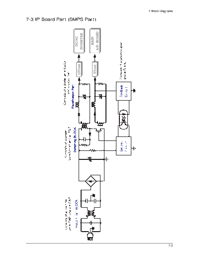
7-3 IP Board Part (SMPS Part)
                                             7-3
7 Block Diagrams
7-4 IP Board Part (Inverter Part)
7-4
                                          13 Circuit Descriptions

13-1-3 IP BOARD BLOCK(POWER) Parts


13-1-4 IP BOARD BLOCK( INVERTER ) Parts


                                                            13-3
13 Circuit Descriptions

13-1-5 IP BOARD(inverter) PROTECTION Parts
PROTECTION Parts


- PROTECTION Parts are divided two parts. When lamp voltage rose as absurd and lamp feedback electric
  current would not be sensed. So all of the two halt IP-Board's function that prevent action the enemy more
  than IP-Board's continous abnormality action.
- When Trans output voltage rose as absurd, become OVP and halts IP-board's function because the
  divided voltage is inputted by IC(U201) 2 PIN.
- When lamp current is sensed, become OLP and halts IC because the IC(U201) 2 PIN is became
   under 2.5V


13-4
                                                                      13 Circuit Descriptions

13-2 Trouble Shooting
13-2-1 IP BOARD(Power)


                                         Power On


                  No
                                     Check Fuse (F101)


                                       Yes

       Change FUSE
                                       IC101 Vst-Pin
        No                             (Norma:High)
                                                                              No

 Check the short of AC part or                                      Check the IC
                                       Yes
         IC101 D-pin


                                       IC101 Vcc-Pin
                  No                  (Normal:9~16V)
                                                                              No

  Check the 13V output part                                       Check the Vcc part
            open                       Yes


                                        IC101 D-Pin
                                     (Normal:Switching)
                                                                              No


                                        Yes                    Check the Switching part


                                         Output 13V
                  No                   (Normal:12~14V)
                                                                               No

 Check the protection system            Yes                    Check the feedback system


                                          Inlet/Output
                                            Harness
                                                                               No


                                          Yes                     Check the Pin or wire
                                                                      connection

                                 Check others Harness, Inlet


                                                                                          13-5
13 Circuit Descriptions

13-2-1 IP BOARD(Inverter)


                                          Power On


                                      Check the 13V line
                                                                               No

                                        Yes                     Check the Adapter system


                                           16Pin
                                       (Normal:5Vtyp.)
                                                                               No


                                        Yes                      Check the Input Circuit


                                          Control IC is
                                  (Pin 12, 13 : chopping wave
                                     Pin 8, 9 : square wave)                   No


                                         Yes                    Check the Control IC & IC
                                                                         Driver

                                         Inverter Trans
                    No               (Pin8,9 : square wave)
                                                                                No

   Check the Protection Circuit           Yes                   Check the Half-bridge part


                                         Output Current
                     No                 (Normal Output)
                                                                                 No

    Check the Dimming Circuit                                   Check the Feedback Circuit
                                           Yes


                                  Check others Harness, Inlet


13-6
                                          13 Circuit Descriptions
13-3 IP BOARD(Power) Schematic Diagrams
                                                            13-7
13 Circuit Descriptions
13-4 IP BOARD(Inverter) Schematic Diagrams
13-8


◦ Jabse Service Manual Search 2024 ◦ Jabse PravopisonTap.bg ◦ Other service manual resources online : FixyaeServiceinfo