Service Manuals, User Guides, Schematic Diagrams or docs for : Samsung LCD TV LE40R82BX LE40R82BXXEC
<< Back | HomeMost service manuals and schematics are PDF files, so You will need Adobre Acrobat Reader to view : Acrobat Download Some of the files are DjVu format. Readers and resources available here : DjVu Resources
For the compressed files, most common are zip and rar. Please, extract files with Your favorite compression software ( WinZip, WinRAR ... ) before viewing. If a document has multiple parts, You should download all, before extracting.
Good luck. Repair on Your own risk. Make sure You know what You are doing.
Image preview - the first page of the document
>> Download LE40R82BXXEC documenatation <<
Text preview - extract from the document
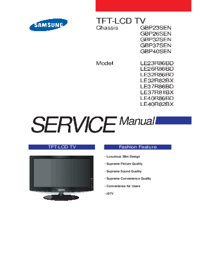
TFT-LCD TV
Chassis GBP23SEN
GBP26SEN
GBP32SEN
GBP37SEN
GBP40SEN
Model LE23R86BD
LE26R86BD
LE32R86BD
LE32R82BX
LE37R86BD
LE37R81BX
LE40R86BD
LE40R82BX
SERVICE Manual
TFT-LCD TV Fashion Feature
- Luxurious Slim Design
- Supreme Picture Quality
- Supreme Sound Quality
- Supreme Convenience Quality
- Convenience for Users
- iDTV
Copyright Trademarks
2007 by Samsung Electronics Co., Ltd. Samsung is the registered trademark of Samsung
Electronics Co., Ltd.
All rights reserved.
LE23R86BD/LE26R86BD/LE32R86BD/
This manual may not, in whole or in part, be copied, LE32R82BX/LE37R86BD/LE37R81BX/LE40R86BD/
photocopied, reproduced, translated, or converted to any LE40R82BX Service Manual and Macmaster Cable
electronic or machine readable form without prior Adapter are trademarks of Samsung Electronics Co.,
written permission of Samsung Electronics Co., Ltd. Ltd.
LE23R86BD/LE26R86BD/LE32R86BD/
Macintosh and Power Macintosh are trademarks of
LE32R82BX/LE37R86BD/LE37R81BX/LE40R86BD/
Apple Computer, Inc.
LE40R82BX Service Manual
All other trademarks are the property of their respective
First edition March 2007.
owners.
Printed in Korea.
ii
Contents
1. Precautions .........................................................................................................................................................1-1
1
1-1 Safety Precautions ....................................................................................................................................... 1-1
1-2 Servicing Precautions ........................................................................... 1-2
1-3 Static Electricity Precautions ........................................................................ 1-2
1-4 Installation Precautions ........................................................................ 1-3
2. Product specifications.................................................................................2-1
2
2-1 Fashion Feature ....................................................................................... 2-1
2-2 LE23R86BD Specifications ........................................................................... 2-2
2-3 LE26R86BD Specifications ........................................................................... 2-3
2-4 LE32R86BD Specifications ........................................................................... 2-4
2-5 LE37R86BD Specifications ........................................................................... 2-5
2-6 LE40R86BD Specifications ........................................................................... 2-6
2-7 Spec Comparison .............................................................................. 2-7
2-8 Option Specification ........................................................................... 2-8
3. Alignments and Adjustments ........................................................................3-1 3
3-1 Service Instruction .............................................................................. 3-1
3-2 How to Access Service Mode ........................................................................ 3-2
3-3 Factory Data .............................................................................. 3-3
3-4 Service Adjustment ........................................................................... 3-11
3-5 Software Upgrade .............................................................................. 3-14
4. Troubleshooting .................................................................................4-1
4
4-1 First Checklist for Troubleshooting ..................................................................4-1
4-2 Checkpoints by Error Mode........................................................................... 4-2
5. Exploded View and Parts List .....................................................................5-1 5
5-1 LE23R86BD Exploded View ........................................................................5-1
5-2 LE23R86BD Parts list ........................................................................... 5-2
5-3 LE26R88BD Exploded View ........................................................................ 5-3
5-4 LE26R88BD Parts list ........................................................................... 5-4
5-5 LE32R82BX Exploded View ........................................................................ 5-5
5-6 LE32R82BX Parts list ........................................................................... 5-6
5-7 LE37R86BD Exploded View ........................................................................ 5-7
5-8 LE37R86BD Parts list ........................................................................... 5-8
5-9 LE40R82BX Exploded View ........................................................................ 5-7
5-10 LE40R82BX Parts list ........................................................................ 5-8
6. Electrical Parts List ...........................................................................6-1 6
6-1 LE40R82BX Parts List ........................................................................ 6-1
7. Block Diagram .................................................................................7-1 7
8. Wiring Diagram .................................................................................8-1 8
8-1Wiring Diagram ..............................................................................8-1
8-2 Main Board Layout .............................................................................. 8-2
8-3 PIN characteristic................................................................................. 8-3
8-4 Connector Location and PCB outline figure ............................................................ 8-6
8-5 Output Connector .............................................................................. 8-7
9. Schematic Diagrams .................................................................................9-1 9
10. Operating Instructions and Installation ...............................................................10-1 1
10-1 Front ....................................................................................... 10-1
10-2 Viewing the Connection Panel .................................................................. 10-2
10-3 Remote control ................................................................................. 10-5
10-4 Installation the Stand ........................................................................ 10-6
10-5 Installing the Wall Mount Kit ..................................................................... 10-6
11. Disassembly and Reassembly.....................................................................11-1 1
11-1 Disassembly .............................................................................. 11-1
11-2 Reassembly .............................................................................. 11-5
12. PCB Diagram ....................................................................................12-1
1
12-1 Main PCB Diagram (Without Card Slot) ............................................................... 12-1
12-2 Main PCB Diagram (With Card Slot) ..................................................................12-2
13. Circuit Descriptions ...........................................................................13-1
1
13-1 Main Signal Description ..................................................................... 13-1
13-2 DTV Signal Description ..................................................................... 13-2
13-3 RF/DTV Tuner (DNOS403MH261B(S)) SPEC. ............................................................ 13-3
13-4 DTV MAIN ChipSet ........................................................................... 13-9
14. Reference Infomation ........................................................................ 14-1
14-1 Technical Terms .............................................................................. 14-1
14-2 Pin Assignments .............................................................................. 14-4
14-3 Timing Chart.............................................................................. 14-7
14-4 Panel Description ........................................................................... 14-11
Contents
Samsung Electronics Co.,Ltd.
- This Service Manual is a property of 416, Maetan-3Dong, Yeongtong-Gu, Suwon City,
Samsung Electronics Co., Ltd. Gyeonggi-Do, Korea, 443-742
Any unauthorized use of Manual can be Printed in Korea
punished under applicable International P/N : BN82-00183B-00
and/or domestic law. URL : http://itself.sec.samsung.co.kr/
3 Alignments and Adjustments
3 Alignments and Adjustments
3-1 Service Instruction
1. Usually, a color TV-VCR needs only slight touch-up adjustment upon installation.
Check the basic characteristics such as height, horizontal and vertical sync.
2. Use the specified test equipment or its equivalent.
3. Correct impedance matching is essential.
4. Avoid overload. Excessive signal from a sweep generator might overload the front-end
of the TV. When inserting signal markers, do not allow the marker generator to distort
test result.
5. Connect the TV only to an AC power source with voltage and frequency as specified on
the backcover nameplate.
6. Do not attempt to connect or disconnect any wire while the TV is turned on. Make sure
that the power cord is disconnected before replacing any parts.
7. To protect aganist shock hazard, use an isolation transform.
3-1
3 Alignments and Adjustments
3-2 How to Access Service Mode
3-2-1 Entering Factory Mode
1. To enter "Service Mode" Press the remote -control keys in this sequence :
- If you do not have Factory remote - control
Power OFF MUTE MENU MUTE Power On
- If you have Factory remote - control
PICTURE ON DISPLAY FACTORY
- The buttons are active in the service mode.
1. Remote - Control Key : Power, Arrow Up, Arrow Down, Arrow Left
Arrow Right, Menu, Enter, Number Key(0~9)
2. Function - Control Key : Power, CH +, CH -, VOL +, VOL -,
Menu, TV/VIDEO(Enter)
3-2-2 Panel Check
You have to check Panel Maker Because of different adjustments as follows.
First of all, Check the label rating!
1) Label Rating File
- LCD PANEL MARK -
A:ACER(AUO) S : SEC C : CMO * If not printed you could consider S(sec) panel mark.
2) If Panel Mark is "A", Set the factory mode indicating as follows.
* Option Byte
1. Inch Option 32"
2. Gamma 32"AUO
3. Panel Option AUO
Others are same shown below.
3-2
3 Alignments and Adjustments
3-3 Factory Data
1. Calibration
2. Service
3. White Balance
4. SVP-UX
5. Option Block
6. SGTV5810/NTP3000
7. YC Delay
8. Option Table
9. I2C Check
10. W/B MOVIE
11. Checksum
12. Reset
13. Spread Spectrum
T-BDPMPEUD-xxxx (Main Micom Ver)
T-BDPMPEUS-xxxx
BORD2_CALLA_TR-xxxx (Sub Micom Ver)
Month / Day / Year / Hour / Min. / Sec.
1. Calibration
1) AV Calibration
2) COMP Calibration
3) PC Calibration
4) HDMI Calibration
2. Option Table XXXX XXXX
No Item Range
1 Ready ON/OFF OFF
2 Inch Option 23"/ 26" / 32"... 32"
3 Panel Vender AUO/CMO... AMLCDINT
4 Gamma ON/OFF OFF
5 Panel Type Normal1/Normal2... Normal1
6 Model Option Calla/Lily/Bord Plus/Jasmine Bord Plus
7 Tuner SEMCO/ALPS SEMCO
8 Tuner TOP 0~31 8
9 Auto Power ON/OFF ON
10 Nordic ON/OFF OFF
11 LNA Menu ON/OFF ON
12 TTX On/Off ON/OFF ON
13 TTX List Flof/List Flof
14 Carrier Mute ON/OFF OFF
15 High Deviation ON/OFF OFF
16 VOL.Curve Small/Large Small
17 HDMI Hotplug 1/0 1
18 HDMI Clock CtrI 1/0 1
19 HDMI Hotplug Dly 3~50 9
3-3
3 Alignments and Adjustments
No Item Range
20 Hotel Option
Hotel Mode ON/OFF OFF
Power On Channel 1~99 1
Power On Volume 1~100 10
Max Volume 1~100 100
Local Key Lock ON/OFF OFF
Power On Source RF/Ext.1... RF
21 Shop Mode ON/OFF OFF
22 Color Space ON/OFF ON
23 PC Ident ON/OFF OFF
24 Language English/German... English
25 ANYNET+ ON/OFF ON
26 Ch.Table SUWON/SESK/SEH/TTSEC SUWON
27 TTX Group Auto/West Europe... Auto
28 iDTV_Cntry UK/France... UK
3. White Balance
No Item Range TV/AV/Scart Comp/iDTV PC HDMI
1 Sub-Briteness 00H~FFH 128 128 128 128
2 R-offset 00H~FFH 128 128 128 128
3 G-offset 00H~FFH 128 128 128 128
4 B-offset 00H~FFH 128 128 128 128
5 Sub-Contrast 00H~FFH 128 128 128 128
6 R-Gain 00H~FFH 128 128 128 128
7 G-Gain 00H~FFH 128 128 128 128
8 B-Gain 00H~FFH 128 128 128 128
4. SVP-PX
1) ComB Filter
No Item Range
1 Y-Filter 00H~FFH
2) Sharpness
No Item Range RF AV Comp480i Comp480p Comp720p Comp1080i HDMI PC iDTV
1 H2Gain 00 ~ 1FH 05H 05H 05H 05H 04H 04H 0AH 05H 05H
2 H4Gain 00 ~ 1FH 04H 0AH 05H 05H 02H 02H 0AH 05H 05H
3 V2Gain 00 ~ 1FH 0CH 0CH 0AH 0CH 0AH 0AH 10H 0AH 0AH
4 V4Gain 00 ~ 1FH 0CH 10H 0CH 0CH 0AH 0AH 10H 0AH 0AH
5 Sr2Gain 00 ~ 1FH 00H 00H 00H 00H 00H 00H 00H 00H 00H
6 Sr4Gain 00 ~ 1FH 00H 02H 00H 00H 02H 02H 04H 02H 02H
7 Sl2Gain 00 ~ 1FH 00H 00H 00H 00H 00H 00H 00H 00H 00H
8 Sl4Gain 00 ~ 1FH 00H 02H 00H 00H 02H 02H 04H 02H 02H
9 Peakth1 00H~FFH 06H 02H 03H 03H 03H 03H 03H 08H 04H
10 Peakth2 00H~FFH 2FH 2FH 2FH 2FH 2FH 2FH 2FH 2FH 2FH
11 Peskth3 00H~FFH 3FH 3FH 3FH 3FH 3FH 3FH 3FH 3FH 3FH
3-4
3 Alignments and Adjustments
3) NR
No Item Range
1 Y_NR_OFF 00H~FFH(Y_NR_OFF) 00H
2 C_NR_OFF 00H~FFH(C_NR_OFF) 00H
3 Y_NR_ON 00H~FFH(Y_NR_ON) 00H
4 C_NR_ON 00H~FFH(C_NR_ON) 00H
4) RGB Calibration
No Item Range TV/AV/S_Video Component PC HDMI
1 R-Offset 00H~FFH 3AH 40H 32H 82H
2 G-Offset 00H~FFH 3AH 40H 32H 82H
3 B-Offset 00H~FFH 3AH 40H 32H 82H
4 R-Gain 00H~FFH A6H 92H A9H 6CH
5 G-Gain 00H~FFH A6H 92H A9H 6CH
6 B-Gan 00H~FFH A6H 92H A9H 6CH
5) ADC Calibration
No Item Range TV/AV/S_Video Component PC HDMI
1 TCD3 Contrast 00H~FFH 79H 78H 78H 78H
2 TCD3 Brightness 00H~FFH 29H 20H 20H 20H
3 TCD3 CR 00H~FFH 80H 80H 80H 80H
4 TCD3 CB 00H~FFH 80H 80H 80H 80H
5 TCD3 Delay 00H~FFH 00H 00H 00H 00H
6 Analog Y Offset 00H~FFH 40H 3DH 44H 40H
7 Analog PB Offset 00H~FFH 80H 80H 44H 80H
8 Analog PR Offset 00H~FFH 80H 80H 44H 80H
9 Analog Y Gain 00H~FFH D6H B3H A4H 80H
10 Analog PB Gain 00H~FFH 80H B3H ACH 80H
11 Analog PR Gain 00H~FFH 80H B3H A7H 80H
12 Black Level 00H~FFH 00H 00H 00H 00H
13 Svp Brightness 00H~FFH 00H 00H 00H 00H
6) Caliration Target
No Item Range low high Delta
1 AV ADC 00H~FFH 10H DCH 02H
2 COMP ADC 00H~FFH 10H EBH 02H
3 PC ADC 00H~FFH 10H DCH 04H
4 ALL RGB 00H~FFH 01H EBH 0AH
3-5
3 Alignments and Adjustments
7) Color Management
No Item Range
1 Skin Direction Reddish/Yellowish Reddish
2 Skin Enhance 00H~FFH 00H
3 Green Stretch 00H~FFH 00H
4 Blue Stretch 00H~FFH 00H
5. Option Block
1) FRC(Micronas)
2) FRC2X
No Item Range
1 OUTCON 1~3 0
2 GAMMA 1~7 0
3 OCC_MODE 0/1 0
4 FALLBACK 0/1 0
5 DBG_MARK 0/1 0
6 SPR_CBR 0/1 0
7 BIT_EXPAND 0/1 0
8 INV_BIT_EXPAND 0/1 0
9 REPEAT_MODE 0/1 0
10 DEMO_ON_OFF 0/1 0
11 MMU_RD_START 00H~FFH 00H
12 ME_RD_START 00H~FFH 00H
13 MC_RD_START 00H~FFH 00H
14 CMZL(0x36E) 00H~0FH 0H
15 BLOL(0x2A7) 00H~0FH 0H
16 LOGO(0x2A7) 00H~0FH 0H
3-6
3 Alignments and Adjustments
3) FBE2
AV/ COMP COMP COMP
No Item Range RF HDMI DTV DTV
S-VIDEO (480i/576i) (480p/576p) (720p/1080i/1080p)
1 Pattern Select 0~20 0 0 0 0 0 0 0 0
2 BS-On 0/1 1 1 1 1 1 1 1 1
3 B-Slope Gain 0~255 34 44 44 64 64 64 64 64
4 B-Tilt Min 0~255 20 20 20 20 20 20 20 20
5 B-Tilt Max 0~255 120 120 120 120 120 120 120 120
6 B-Tilt Slope 0~255 128 128 128 128 128 128 128 128
7 LFunc-Basis 0~255 30 20 20 40 70 55 75 75
8 Hfunc-Basis 0~255 30 40 40 40 75 65 88 88
9 Mean-Offset1 0~255 20 100 100 75 75 75 75 75
10 Mean Offset2 0~255 120 200 200 155 225 225 225 225
11 Mean Slope 0~255 56 56 56 45 85 85 85 85
12 Input Offset 0~255 128 128 128 128 128 128 128 128
13 Input Gain 0~255 128 128 128 128 128 128 128 128
14 ACR Offset 0~128 15 15 15 15 15 15 15 15
15 ACR Th1 0~255 30 30 30 30 30 30 30 30
16 ARC Th2 0~255 130 130 130 130 130 130 130 130
17 Skin Enable 0/1 1 1 1 1 1 1 1 1
18 Skin Tu 0~255 165 165 165 150 165 165 128 128
19 Skin Tv 0~255 140 140 140 140 128 128 128 128
20 M Skin Tu 0~255 128 128 128 128 128 128 128 128
21 M Skin TV 0~255 128 128 128 128 128 128 128 128
22 Sub Color 0~255 115 128 128 135 140 150 143 143
23 M-Au-Sub Color 0~255 128 128 128 128 128 128 128 128
24 M-Wi-Sub Color 0~255 128 128 128 128 128 128 128 128
25 MW-Skin-Tu 0~255 128 128 128 128 128 128 128 128
26 MW-Skin-Tv 0~255 128 128 128 128 128 128 128 128
3-7
3 Alignments and Adjustments
4) Pdp Logic
No Item Range
1 Pattern Srlect 0~63 0
2 Data updata ON/OFF OFF
3 Data Type 42"EU MRT/42"EU MESH/..... 42"EU MRT
4 CDC Sw ON/OFF OFF
5 CDC Strengh Th 0~31 0
6 BRE Sw ON/OFF OFF
7 FRC Repeat Mode ON/OFF OFF
8 FRC CBG Mark On 0~15 0
9 ERC Bypass ON/OFF OFF
10 Panel Type - 0H
11 Panel Inch - SD
12 Panel Version -
13 Logic Sw Version - 0H 0H 0H
6. SGTV5810/NTP3000
No Item Range
1 ID Tone Shift 1H~FH 01H
2 ID Tone Thresh 00H~FFH 7FH
3 Demod Prescaler 00H~20H 13H
4 Master Volume 00H~30H 13H
5 PWM Modulation 80H~F2H F1H
6 DRC Threshold 00H~7FH 06H
7 Speaker EQ ON/OFF OFF
7. YC Delay
No Item Range
1 RF PAL-B/G 00H~FFH AAH
2 RF PAL - D/K 00H~FFH 99H
3 RF PAL - I 00H~FFH 99H
4 RF SECAM - B/G 00H~FFH 88H
5 RF SECAM - D/K 00H~FFH 44H
6 RF SECAM -L/L' 00H~FFH 88H
7 RF NTSC 3.58 00H~FFH 44H
8 RF NTSC 4.43 00H~FFH CCH
9 AV PAL 00H~FFH AAH
10 AV SECAM 00H~FFH 88H
11 AV NTSC 3.58 00H~FFH 30H
12 AV NTSC 4.43 00H~FFH AAH
13 AV PAL60 00H~FFH 77H
3-8
3 Alignments and Adjustments
8. Adjust
No Item Range
1 Video Mute Time 0~255 10
2 Dynamic Contrast ON/OFF OFF
3 Dynamic Dimming ON/OFF ON
4 Dynamic CE ON/OFF OFF
5 LNA PLUS
RFDB-1 Level 0~255 2
RFDB-2 Level 0~255 5
RFDB-3 Level 0~255 7
RFDB-4 Level 0~255 24
6 Magazine LNA ON/OFF OFF
7 PixelShift Test ON/OFF OFF
8 Debug ON/OFF OFF
9 ACR ON/OFF OFF
10 D-Watchdog ON/OFF ON
11 UART Select MAIN / IDTV / PDP Lvds ON / PDP Lvds OFF OFF
9. I2C Check
10. W/B MOVIE
No Item Range TV/AV/S_Video Component PC HDMI Scart1/2
1 WB Movie ON/OFF OFF OFF OFF OFF OFF
2 Color Mode Movie Movie Dynamic Dynamic Dynamic Dynamic
3 Color Tone Cool1 Cool1 Cool1 Cool1 Cool1
4 Msub Brigh 0~255 128 128 128 128 128
5 Msub Contr 0~255 128 128 128 128 128
6 W1_RGAIN 0~255 157 161 144 161 157
7 W1_BGAIN 0~255 76 74 117 76 76
8 W1_R_OFFS 0~255 119 119 127 118 119
9 W1_B_OFFS 0~255 138 140 110 141 138
10 W2_RGAIN 0~255 142 143 149 142 142
8 W2_BGAIN 0~255 48 47 93 51 48
9 W2_R_OFFS 0~255 129 127 124 128 129
10 W2_B_OFFS 0~255 143 145 110 143 143
11 NO_RGAIN 0~255 141 139 137 141 141
12 NO_BGAIN 0~255 104 102 123 104 104
13 NO_R_OFFS 0~255 126 125 126 121 126
14 NO_B_OFFS 0~255 136 133 114 133 136
15 C2_RGAIN 0~255 124 122 123 125 124
16 C2_BGAIN 0~255 142 141 156 143 142
17 C2_R_OFFS 0~255 128 129 117 128 128
18 C2_B_OFFS 0~255 128 127 116 128 128
19 Movie Contr 0~100 100 100 100 100 100
20 Movie Brigh 0~100 45 45 45 45 45
21 Movie Color 0~100 55 55 55 55 55
22 Movie Sharp 0~100 75 75 75 75 75
3-9
3 Alignments and Adjustments
11. Checksum 7A72
12. Reset
13. Spread Spectrun
No Item Range
1 Spectrum ON/OFF ON
2 Delta -128 ~ +128 0
3 Positive 0~99 8
4 Negative 0~99 2
5 Speed 0~7 0
6 Time 0~7 4
7 FBE Spectrum ON/OFF OFF
8 FEE Delta 0~5 0
3-10
3 Alignments and Adjustments
3-4 Service Adjustment
3-4-1 White Balance - Calibration
If picture color is wrong, do calibration first.
Equipment : CA210, Patten : chess pattern
Execute calibration in Factory Mode
Source AV : PAL composite, Component : 1280*720/60Hz
PC : 1024*768/60Hz
( chess patten )
3-4-2 White Balance - Adjustment
If picture color is wrong, check White Balance condition.
Equipment : CA210, Patten : Flat W/B Pattern
Adjust W/B in Factory Mode
Sub brightness and R/G/B Offset controls low light region
Sub contrast and R/G/B Gain controls high light region
Source AV : PAL composite, Component : 1280*720/60Hz
HDMI[DVI] : 1280*720/60Hz
[ Test Pattern : MIK K-7256 PAttern #92 ]
*Color temperature
1500K +/-500, -6 ~-20 MPCD
*Color coordinate
H/L : 267/263 +/- 2 35.0 Ft +/- 2.0Ft
L/L : 270/260 +/- 3 1.5 Ft +/- 0.2Ft
Flat W/B Pattern
3-11
3 Alignments and Adjustments
3-4-3 Conditions for Measurement
1. On the basis of toshiba ABL pattern : High Light level (57 IRE)
- INPUT SIGNAL GENERATOR : MSPG-925LTH
* Mode NO 2 : 744X484@60 Hz
NO 6 : 1280X720@60 Hz
NO 21 : 1024X768@60 Hz
* Pattern NO 36 : 16 Color Pattern
NO 16 : Toshiba ABL Pattern
2. Optical measuring device : CA210 (FL)
Please use the MSPG-925 LTH generator for model LE26M51B/LE32M51B/LE40M51B/LE46M51B.
3-4-4 Method of Adjustment
1. Adjust the white balance of AV, Component and DVI Modes.
(AV Component)
a) Set the input to the mode in which the adjustment will be made
(RF DTV PC DVI).
* Input signal - VIDEO Mode : Model #2 (744*484 Mode), Pattern #16
- DTV,DVI Mode : Model #6 (1280*720 Mode), Pattern #16
- HDMI Mode: Model #6(1280*720 Mode), Pattern #16
b) Enter factory color control, confirm the data.
c) Adjust the low light. (Refer to table 1, 2 in adjustment position by mode)
- Adjust sub - Brightness to set the 'Y' value.
- Adjust red offset ('x') and blue offset ('y') to the color coordinates.
Picture 4-2 Flat W/B Pattern
Low light
Measurement point
* Do not adjust green offset data.
d) Adjust the high light. (Refer to table 1, 2 in adjustment position by mode)
- Adjust red gain ('x') and blue gain ('y') to the color coordinates.
* Do not adjust the green gain and sub-contrast (Y) data.
3-12
3 Alignments and Adjustments
d) Adjust the high light. (Refer to table 1, 2 in adjustment position by mode)
- Adjust red gain ('x') and blue gain ('y') to the color coordinates.
* Do not adjust the green gain and sub-contrast (Y) data.
Picture 4-3 Flat W/B Pattern
High light
Measurement point
3-13
3 Alignments and Adjustments
3-5 Software Upgrade
3-5-1 How to Update Flash ROM
1. Install the Flash Downloader
ConnectSet(Service Jack)and Jig Cable to execute Program Update.
2. Flash Downloader program update
-Before Turning on the set,Click "connect"which is under of OSD Screen!
-Turn on the Set.
3-14
7 Block Diagrams
7 Block Diagram
- This Document can not be used without Samsung's authorization
7-1
7 Block Diagrams
Memo
7-2
13 Circuit Descriptions
13 Circuit Descriptions
13-1 Block description
Signal
Power
IP Board
RF IN
Scart 1,2
A/V
S-Video Main
Board Panel
Component T-con
Board
HDMI 1, 2
PC
Speaker
IR/LED
Bordeaux consists of three main blocks
1. Main board : Video signal processing
2. IP board : Power supply & Inverter
3. T-con board : LCD Panel control
13-1
13 Circuit Descriptions
Signal
Power SMPS INVERTER
RF IN
Scart 1,2
A/V
S-Video Main
Board Panel
Component T-con
Board
HDMI 1, 2
PC
Speaker
IR/LED
Bordeaux consists of three main blocks
1. Main board : Video signal processing
2. SMPS : Power supply
3. T-con board : LCD Panel control
13-2
13 Circuit Descriptions
13-2 Main Block
13-3
13 Circuit Descriptions
13-3 SMPS Board
13-3-1 23" Power Block
Line PFC Inverter
Resonance
Filter AC Switching PFC Resonance SMPS
Switching
Part Rectifier Part Rectifier Transformer Output 24V
Part
Rectifier
Part Signal
DC/DC
MC33167 5.3V
AC Input PFC Resonance
(90Vac~264Vac) Controler Controller
Signal
TDA4863 MC33067
13V
Regulator Sound
On/Off KA78R09 12V
Control
On/Off
Stand-By
Controller Output
ST-BY Stand-By
VIPer12A Rectifier
Transformer 5.2V
Part
13-3-2 23" SMPS Diagram
PFC PFC DC Current
Rectifier Output Resonant Type Trans EER3944
EMI INVERTER
FILTER 24V
INPUT
450V
AC Input 150uF
90V~264V TDA4863 Main
+13V
F222L Regulator
Sound
+9V
Trans EE2020
DC/DC V5D
Converter +5.3V
VIPer12A
Stand-By
5.2V
On/Off Power On/Off
Control Signal
13-4
13 Circuit Descriptions
Output Voltage Output Current
Output
Load Characteristics PCB Loc. Usage Remark
Name
Normal Regulation(%) Variable Range Min Typical Peak
24V 24.5V ◦ Jabse Service Manual Search 2024 ◦ Jabse Pravopis ◦ onTap.bg ◦ Other service manual resources online : Fixya ◦ eServiceinfo