Service Manuals, User Guides, Schematic Diagrams or docs for : Samsung Laptop samsung q1u

<< Back | Home

Most service manuals and schematics are PDF files, so You will need Adobre Acrobat Reader to view : Acrobat Download Some of the files are DjVu format. Readers and resources available here : DjVu Resources
For the compressed files, most common are zip and rar. Please, extract files with Your favorite compression software ( WinZip, WinRAR ... ) before viewing. If a document has multiple parts, You should download all, before extracting.
Good luck. Repair on Your own risk. Make sure You know what You are doing.


Image preview - the first page of the document
samsung q1u


>> Download samsung q1u documenatation <<

Text preview - extract from the document
-          -
- This Document can not be used without Samsung's authorization -


3. Disassemble and Assemble

1) Q1 Ultra Disassemble and Assemble                       * Attention to red sentence.
  Part                  Picture                                  Description
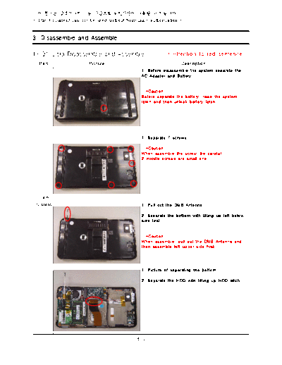
                                               1. Before disassemble the system separate the
                                               AC Adapter and Battery


                                                  *Caution
                                               Before separate the battery, raise the system
                                               latch and then unlock battery latch.


                                               1. Separate 7 screws.

                                                 *Caution
                                               When assemble the screw, be careful
                                               2 middle screws are small one.


  Main
 System                                        1. Pull out the DMB Antenna

                                               2. Separate the bottom with lifting up left below
                                               side first


                                                 *Caution
                                               When assemble, pull out the DMB Antenna and
                                               then assemble left upper side first.


                                               1. Picture of separating the bottom.

                                               2. Separate the HDD with lifting up HDD latch.


                                             3-1
- This Document can not be used without Samsung's authorization -


3. Disassemble and Assemble

  Part                  Picture                                 Description
                                               1. Separate Audio cable and Mic cable from
                                               connector

                                               2. Separate 4 screws of DMB Module and DMB
                                               Antenna.


                                               1. Picture of separating DMB antenna and DMB
                                               module.


                                               2. Separate the 5 screws of Main Board.


  Main
 System                                        1. Separate Sub_R, Sub_L, T-Con FPC.

                                                  *Caution
                                               When separating FFC, be careful not to brake
                                               of connector pin.
                                               When assemble, assemble the T-Con FPC
                                               exactly.


                                               1. up side down the Maini Board and then
                                               separate AUX Antenna cable.(Black cable)

                                                 *Caution
                                               When assemble the AUX Cable, using tape for
                                               exacting assemble.


                                             3-2
- This Document can not be used without Samsung's authorization -


3. Disassemble and Assemble

  Part                  Picture                                  Description
                                               1. Picture of being separated Main Board.


  Main
 System


                                               1. Remained LCD Part after separate Main Board.

                                               2. Separate 2 screws which is fixing LCD Top
                                               and LCD bracket.


  LCD
                                               1. LCD part after separate LCD bracket.


                                             3-3
- This Document can not be used without Samsung's authorization -


3. Disassemble and Assemble

  Part                  Picture                                  Description
                                               1. Separate silver tape which connect LCD
                                               module and T-Con board.

                                               2. Separate 7 FPCs which is connected to T-
                                               Con B'd.


                                               1. Separate T-Con board with lifting up the lcd
                                               latch and sliding right side.


  LCD
                                               1. Separated T-Con board.


                                               1. Picture of LCD part (separated LCD module)

                                               2. Separate Right/Left FFC.


                                             3-4
- This Document can not be used without Samsung's authorization -


3. Disassemble and Assemble

  Part                  Picture                                  Description
                                               1. Picture after separate FFC.

                                               2. Lifting up LCD module.


                                               1. Separated LCD module.


  LCD                                          1. Picture which is separated LCD module.


                                               1. Separate Left Touch Button FFC from
                                               connector.

                                               2. Separate 2 screws which is connecting TOP
                                               and Left board.


                                             3-5
- This Document can not be used without Samsung's authorization -


3. Disassemble and Assemble

  Part                  Picture                                  Description
                                               1. Separated picture.

                                               From upper side, Hall MOUSE, LEFT B'd, Finger
                                               print B'd


                                               1. Separate Right Key pad FCT from Right B'd.

                                               2. Separate 2 screws which is connected with
                                               LCD Top.


  LCD
                                               1. Separated picture.

                                               From upper side, Right Board and Bluetooth.


                                               1. Picture of Camera B'd is connected with LCD
                                               Top.

                                               2. Separate the camera module with
                                               disassembling 2 screws.


                                             3-6
- This Document can not be used without Samsung's authorization -


3. Disassemble and Assemble

  Part                  Picture                                  Description
                                               1. Separated camera module.


                                               1. Picture which Left Key pad and bracket is
                                               fixed to TOP.

                                               2. By pushing inside of the 4 latchs which
                                               fixing bracket, separate the Key pad FPC.


  LCD
                                               1. Picture which Right Key pad and bracket is
                                               fixed to TOP.

                                               2. By pushing inside of the 4 latchs which
                                               fixing bracket, separate the Key pad FPC.


                                               1. Picture of separated Right/Left Key pad FPC.


                                             3-7


◦ Jabse Service Manual Search 2024 ◦ Jabse PravopisonTap.bg ◦ Other service manual resources online : FixyaeServiceinfo