Service Manuals, User Guides, Schematic Diagrams or docs for : Samsung Laptop samsung q40
<< Back | HomeMost service manuals and schematics are PDF files, so You will need Adobre Acrobat Reader to view : Acrobat Download Some of the files are DjVu format. Readers and resources available here : DjVu Resources
For the compressed files, most common are zip and rar. Please, extract files with Your favorite compression software ( WinZip, WinRAR ... ) before viewing. If a document has multiple parts, You should download all, before extracting.
Good luck. Repair on Your own risk. Make sure You know what You are doing.
Image preview - the first page of the document

>> Download samsung q40 documenatation <<
Text preview - extract from the document
.
This Document can not be used without Samsung's authorization.
4. Assembly and Disassembly
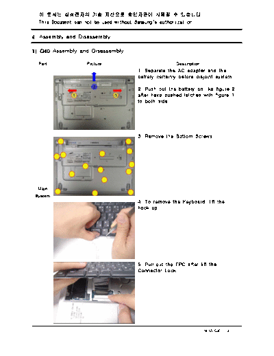
1) Q40 Assembly and Disassembly
Part Picture Description
1. Separate the AC adapter and the
battery certainly before disjoint system.
2. Push out the battery on like figure 2
after have pushed latches with figure 1
to both side
3. Remove the Bottom Screws.
Main
System
4. To remove the Keyboard, lift the
hook up.
5. Pull out the FPC after lift the
Connector Lock.
SENS Q40 < 4 - 1 >
.
This Document can not be used without Samsung's authorization.
4. Disassembly and Assembly
Part Picture Description
6. Remove the Thermal Plate Screw
(4ea).
7. Remove the Hinge Cap by using
the tweezers.
Main
System
8. Remove the screws(2EA) and LCD
cable screw(1EA) at yellow circle that
combine Hinge and Top.
9. Pull out the LCD cable and detach
the LCD Assy
( Caution : When separate the Antenna cable
first separate antenna from Bottem by using
tweezers then separate each antenna by using
hand cautiously)
SENS Q40 < 4 - 2 >
.
This Document can not be used without Samsung's authorization.
4. Disassembly and Assembly
Part Picture Description
10. Afer saparating the LCD Assy,
remove the 3 in 1 Dummy card and
TOP screw(2 EA).
11. Lift up the HDD Connector then
11.
separate HDD FPC andHDD
Main
System
12. Separate the TOP and Bottom
pulling out the TOP like arrow direction.
( Caution : Separate the Top cautioously not
to be broken.)
13. Separate the Touchpad FPC from
Main Board's Connector
SENS Q40 < 4 - 3 >
.
This Document can not be used without Samsung's authorization.
4. Disassembly and Assembly
Part Picture Description
14. Disassemble the Power, Bluetooth,
Speaker, RTC Batt,
Wireless Lan, cable of Docking
Connector (reference the blue mark).
15. Remove the Screws of Option
board(8EA)
Main
System
16. This is the picture of disassembled
material
17. Remove the screws(5 ea) which
assemble the bottom and main board
And remove the docking connector also
SENS Q40 < 4 - 4 >
.
This Document can not be used without Samsung's authorization.
4. Disassembly and Assembly
Part Picture Description
18. This is the picture of detached main
board from bottom.
19. This is the picture of detached
bottom
Main
System
20. This is the picture that separate the
docking FPC and speakers
SENS Q40 < 4 - 5 >
.
This Document can not be used without Samsung's authorization.
4. Disassembly and Assembly
Part Picture Description
1. Removing the Rubber Foot(4EA).
( Caution : be careful occuring the
any scratch.)
2. Remove the screws(4EA) indicated at
picture
LCD
3. Lift the LCD front(downward direction)
up slowly from the bottom end by using
your hand.
.
4. Remove the Screws(4EA) which
assembled LCD Hinge and screw(2EA)
which assembled LCD inverter board
and screw(1EA) which assembled LCD
cable ring.
SENS Q40 < 4 - 6 >
.
This Document can not be used without Samsung's authorization.
4. Disassembly and Assembly
Part Picture Description
5. This is the picture after disassembling
6. Disassemble the LCD Cable and LCD
Invertor
LCD
7. Disassemble the screws(4 EA) which
fix the each side of LCD bracket
8. This is the picture after finishing
SENS Q40 < 4 - 7 >
.
This Document can not be used without Samsung's authorization.
4. Disassembly and Assembly
Part Picture Description
1. This is the picture of Top case which
is separate from bottom.
2. Remove the screws(5ea) which fixing
Top and LED FPC then lift up the
Touch pad connector.
TOP
Assy
3. Separated Top.
4. Separated LED FPC
SENS Q40 < 4 - 8 >
.
This Document can not be used without Samsung's authorization.
4. Disassembly and Assembly(Main B'd Modem, Bluetooth )
Part Picture Description
1. This is the picture of Main Board
which is separated from bottom.
2. Remove the screws(2ea) which is
fixing Modem and Bluetooth.
Main
Board
3. Separate the Modem like the picture.
4. Separate the Modem cable like the
picture.
SENS Q40 < 4 - 9 >
.
This Document can not be used without Samsung's authorization.
Part Picture Description
5. Separate the Bluetooth cable like the
picture.
( Caution : When separate the cable, be
careful do not break down Bluetooth cable.)
6. Remove the screw which is fixing the
3 in 1 Board.
Main
Board
7. Separate the 3 in 1 Board like the
picture.
8. Remove the tape which is attached
on the RTC cable.
SENS Q40 < 4 - 10 >
.
This Document can not be used without Samsung's authorization.
Part Picture Description
9. Separate the RTC battery cable like
the picture.
10. Picture of PCB which remove the all
items.
Main
Board
SENS Q40 < 4 - 11 >
◦ Jabse Service Manual Search 2024 ◦ Jabse Pravopis ◦ onTap.bg ◦ Other service manual resources online : Fixya ◦ eServiceinfo