Service Manuals, User Guides, Schematic Diagrams or docs for : Samsung Projector SP-A400B Wiring Diagram

<< Back | Home

Most service manuals and schematics are PDF files, so You will need Adobre Acrobat Reader to view : Acrobat Download Some of the files are DjVu format. Readers and resources available here : DjVu Resources
For the compressed files, most common are zip and rar. Please, extract files with Your favorite compression software ( WinZip, WinRAR ... ) before viewing. If a document has multiple parts, You should download all, before extracting.
Good luck. Repair on Your own risk. Make sure You know what You are doing.


Image preview - the first page of the document
Wiring Diagram


>> Download Wiring Diagram documenatation <<

Text preview - extract from the document
                                                            CN102    C/W motor
                        DMD Board                                   sensor board
                                                            CN101
                                           CN103
                                         140 Pin
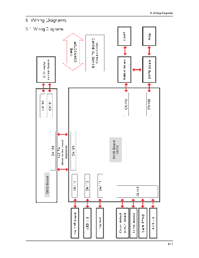
                                                                                                  6-1. Wiring Diagrams


                                    (Refer to the Circuit
                                                                                                                         6. Wiring Diagrams


                                         Diagrams)

                                                                                 WIRE
                         CN113             CN105
      front IR board                                                          CONNECTOR


         LED x 3         CN112
                                                                           BOARD TO BOARD
                                                                             CONNECTOR
         Keypad          CN111


                                         MAIN Board
                                             CN110
      Cover detect
      switch board                                          CN110   Ballast board         LAMP

      Temp sensor
                       CN109
       Light Effect
                                                            CN103   SMPS board            Inlay
         FAN x 3
                                                                                                                                              6. Wiring Diagrams


6-1
                                     Connect the DMD board to the Color wheel


6-2
                         DMD board                                        Connect the IR board               Lamp
                                                                                                                                                                    6. Wiring Diagrams

                                                                                                                                6-1-1. Engine Part Wiring Diagram


      Connect fan1


                                                                                                 Connect the LED board


                                                                                     Connect the temperature detection sensor


                                                                                                  Connect fan2 and fan3

          Connect the ballast
                            Ballast: Operates the lamp


                                                                               Connect the Main board and the DMD board


      Connect the ballast to the SMPS


                                                                                             Connect the inlet to the SMPS
                                                                                                                             6-1-2. Circuit Part Wiring Diagram (Except for the Main board)


                     Main board
                                                                                                                                                                                              6. Wiring Diagrams


6-3
                                                         SMPS   Light effect
                                                                    Connect the ballast   Connect the touch keypad    Connect the LED board   IConnect the IR board


6-4
                 Connect the cover detection switch
                                                                                                                                                                                                         6. Wiring Diagrams


      Connect the temperature detection sensor
                                                                                                                                                                      6-1-3. Main Board Wiring Diagram


                                                 Connect the light effect                    Connect fan1, 2, and 3                      Connect the SMPS
                                                                                                          6. Wiring Diagrams

6-2. Connector Functions and their Connection Errors
 Main Board

    Connector                           Parts to Connect and Connection Error Symptoms

                R Board: Transmits the signals received from the IR receiver to the digital board to operate the projector.
     CN113       When a connection error occurs, the projector does not operate when using the remote control at the
                 front of the projector..
                LED Board: Displays the projector operating status via the LED indicators.
     CN112
                 When a connection error occurs, the LED indicators do not operate.
                Touch Keypad: Transmits the signals received from users to the digital board to operate the projector.
     CN111
                 When a connection error occurs, the Touch keypad does not operate.
                Pin 1,2,3     Fan 1, 2, 3: Decreases the internal temperature of the projector. They turn the projector off when
                Pin 4,5,6     the fan connections are abnormal.
                Pin 7,8,9     When a connection error occurs, the Temp and Standby LEDs blink.
                              Light Effect: This is a light effect to the outside of the projector. It can be turned on or off
                Pin 10,11     depending on the product settings.
                               When a connection error occurs, the Light Effect does not operate.
     CN109                    Temperature Detection Sensor: Detects the internal temperature of the projector. When the
                              internal temperature rises abnormally high, the sensor sends a signal to the digital board to
                Pin 12,13     protect the projector.
                               When a connection error occurs, the Temp LED blinks..
                              Cover Detector: Checks whether the lamp cover covering the lamp is closed correctly. If
                Pin 14,15     incorrect, the cover detector sends a signal to the digital board turning the projector off.
                               When a connection error occurs, the Temp and Lamp LEDs blink.
                Ballast: Controls the lamp operation.
     CN110
                 When a connection error occurs, the lamp does not turn on.
                SMPS: Receives AC power from the outside and supplies voltage to the Main board and the ballast.
     CN103
                 When a connection error occurs, power is not supplied to the projector..
                DMD Board: Transmits the video signal output of the Main board to operate the DMD panel.
     CN105
                 When a connection error occurs, a blank screen is displayed.


 DMD Board

    Connector                           Parts to Connect and Connection Error Symptoms

                Main Board: Receives various video signals and control signals to control or operate the DMD board,
                cooling fan, SMPS board, lamp, and the Ballast. It processes video signals and transmits them to the
     CN103      DMD board.
                 When a connection error occurs, a blank screen is displayed.
                Color Wheel: Rotates and operates as a RGB color filter and thereby gives color to images.
     CN102
                 When a connection error occurs, the Color Wheel does not operate, and the lamp is not turned on.
                Sensor Board: Detects the position of the RGB color filter that rotates on the Color wheel.
     CN101
                 When a connection error occurs, the Color Wheel does not operate, and the lamp is not turned on.


                                                                                                                           6-5
6. Wiring Diagrams

 MAIN Board

                   CN113                                   CN111
      1    P3P3V                               1    P3P3V
      2    GND                                 2    KEYPD_PWR_DDP
      3    IR_FRONT                            3    KEYPD_RIGHT
                                               4    KEYPD_LEFT
                   CN112
           P5V                                 5    KEYPD_DOWN
      1
           LED_PWR                             6    KEYPD_UP
      2
           LED_HOT                             7    KEYPD_SELECT
      3
           LED_LAMP                            8    KEYPD_MENU
      4
           GND                                 9    KEYPD_SOURCE
      5
                                               10   GND
                           CN109
                                                           CN110
      1    FAN3                 FAN3
                                               1    OB_LAMPLITZ
      2    (Lamp cooling        FAN_ECO
                                               2    GND
      3    fan)                 FAN_12V
                                               3    P5V
      4    FAN2                 FAN_TACHO
                                               4    LAMPCTRL
      5    (Ballast cooling     FAN2_FB
                                               5    UART1_TXD
      6    fan)                 FAN2_11VO
      7                         FAN1                       CN102
           FAN1                                1    GND
      8                         FAN_ECO
           (Main cooling fan)                  2    POWER_SW
      9                         FAN_12V
      10                        D5V            3    GND
           Light Effect                        4    P12V_FAN
      11                        LIGHT_EFFECT
      12                        GND            5    GND
           Temp sensor                         6    P12V
      13                        CHK_TEMP
      14                        GND            7    P12V
           Cover Protection
      15   switch               CHK_COVER      8    GND


 DMD Board


                           CN101
               1     P3P3V_CW
               2     CW_SENSE
               3     GND
               4     GND


                           CN102
               1     OUTA
               2     OUTB
               3     OUTC
               4     CWCTR


6-6
                                                                                    6. Wiring Diagrams

 Main Board - Top


 Reference             Parts                              Functions

IC124        DDP2230           Processes video signals, and operates the Micom and the DMD panel

IC121        FLASH memory      The memory to store software

                               Generates the power to operate the DMD Panel by receiving
IC130        DAD2000
                               adjustments from the DDP2230

IC129        PMD1000           Generates the power to operate the DDP2230 and various ICs.

IC122        XDR DRAM          The memory to operate the DDP2230.

                               Decodes Composite and S-video signals (NTSC, PAL, and SECAM)
IC116        TVP5146
                               and transmits them to the DDP2230.

                               Decodes RGB, HDMI, and Component signals and transmits them to
IC117        MST3385
                               the DDP2230.


                                                                                                   6-7
6. Wiring Diagrams

 Main Board - Bottom


 Reference              Parts                                Functions

 U104          SDRAM             The memory to operate the DDP2230.

 IC128         CLOCK GENERATOR   Generates the clock signals to operate the DDP2230.

 IC126         CLOCK GENERATOR   Generates the clock signals to operate the XDR Dram.

 IC118         EEPROM            Stores the settings.


6-8
                                                                                     6. Wiring Diagrams

 DMD board
                   Top side                                      Bottom side


 Reference            Parts                               Functions

IC101        EEPROM           Stores the settings.

                              The panel that displays the video signals received from the DDP2230
IC102        DMD panel
                              as a video image.


                                                                                                    6-9
6. Wiring Diagrams

Memo


6-10


◦ Jabse Service Manual Search 2024 ◦ Jabse PravopisonTap.bg ◦ Other service manual resources online : FixyaeServiceinfo