Service Manuals, User Guides, Schematic Diagrams or docs for : Samsung Refridgerators RS25H5111SR_AA Service Manual SSEDA-14-RS25H51-131221_SCHEMATIC_DIAGRAM

<< Back | Home

Most service manuals and schematics are PDF files, so You will need Adobre Acrobat Reader to view : Acrobat Download Some of the files are DjVu format. Readers and resources available here : DjVu Resources
For the compressed files, most common are zip and rar. Please, extract files with Your favorite compression software ( WinZip, WinRAR ... ) before viewing. If a document has multiple parts, You should download all, before extracting.
Good luck. Repair on Your own risk. Make sure You know what You are doing.


Image preview - the first page of the document
SSEDA-14-RS25H51-131221_SCHEMATIC_DIAGRAM


>> Download SSEDA-14-RS25H51-131221_SCHEMATIC_DIAGRAM documenatation <<

Text preview - extract from the document
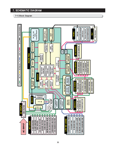
                                                                                AC         DC Source             13V                  5V         Communication
                           AC INPUT
     AC-
     AC-INPUT              EMI-FILTER


         AC LOAD                                                                                       MAIN PBA
                                                                                                                                                                  7-1) Block Diagram


                                        MICOM                     INV COMP
       F-DEF HEATER                                                               DIODE-Option     RESET     EEPROM     OSCILLATOR          Over Voltage
                                                                  CONTROL                                                                    DC 5V, 13V
                                                                                                                                             Protection
                                                                                                                                               from
       R-DEF HEATER
                                 S
                                                                                                                                            Inverter-Board


                                                       n
        PIPE HEATER              M                                             MICOM
                                 P       S
     ICE ROUTE MOTOR             S       P
                                                                   COMP
                                                                                                                                                                                       7. SCHEMATIC DIAGRAM


                                         M                                                                 EEPROM
                                                                                      TEST MODE


                                               Location
                                               Detection
       AUGER MOTOR                                                CONTROL                                  CONTROL
                                                                                       CONTROL
        CUBE MOTOR                                                                                                      UART(PLC)            UART (PLC)
                                                                   LOAD              NORMAL MODE                                           COMMUNICATION
     WATERSOLENOIDVALVE                                                                                                 CONTROL
                                                                  CONTROL              CONTROL
     ICE SOLENOID VALVE                  INV
                               OLP      COMP                         SWITCH          CONDITIONAL
                                                                                             1                                UART             UART
     DISPENSER HEATER                                                 INPUT            CONTROL                              CONTROL        COMMUNICATION
     ICE MAKER HEATER            AC CONTROL
                                   CIRCUIT                                ICE-MAKER              A/D
                                                                           CONTROL            CONVERTER


70
                                 DC CONTROL
                                   CIRCUIT                                                                             5V
                                                            ICE-MAKER CIRCUIT
      13V DC LOAD                                                                                                     13V
                                     SWITCH                 MOTOR        HEATER        TEMP-SENSOR      RH-SENSOR
     COMPRESS COOL FAN               SENSING               CONTROL      CONTROL          S S G
                                                                                         SENSING         SENSING
                                                                                                         S S G

        F-ROOM FAN
        R-ROOM FAN                                                                                                                              PANEL
                                 SWITCH                      ICE-MAKER                  Temp-SENOR               RH-SENOR
     F-ROOM [LED] LAMP          F-DOOR S/W                                                                                                       MICOM
                                                               TEST S/W
                                                                                        F-ROOM SENSOR           EXT-RH SENSOR
     R-ROOM
     R ROOM [LED] LAMP          R-DOOR S/W                  HORIZONTAL S/W                                                                 Touch KEY Sensing
                                                                                        R-ROOM SENSOR
     SEMI C-ROOM BOX FAN      R-HOME BAR S/W                 ICE-FULL S/W                                                                      LED Driver
                                                                                         F-DEF SENSOR
                                                            ICE MAKER SENSOR            R-DEF SENSOR                                         Buzzer Control

                                                                                       AMBIENT SENSOR                                       Semi C-ROOM Control
                                                             EJECT MOTOR

                                                             EJECT HEATER                                                                         PLC
                                                                                                                                              PLC Module
SCHEMATIC DIAGRAM

 7-2) Block Diagram (INVERTER PBA)


                                     71


◦ Jabse Service Manual Search 2024 ◦ Jabse PravopisonTap.bg ◦ Other service manual resources online : FixyaeServiceinfo