Service Manuals, User Guides, Schematic Diagrams or docs for : Samsung Washer WF448AAP_XAA PCB_Diagram

<< Back | Home

Most service manuals and schematics are PDF files, so You will need Adobre Acrobat Reader to view : Acrobat Download Some of the files are DjVu format. Readers and resources available here : DjVu Resources
For the compressed files, most common are zip and rar. Please, extract files with Your favorite compression software ( WinZip, WinRAR ... ) before viewing. If a document has multiple parts, You should download all, before extracting.
Good luck. Repair on Your own risk. Make sure You know what You are doing.


Image preview - the first page of the document
PCB_Diagram


>> Download PCB_Diagram documenatation <<

Text preview - extract from the document
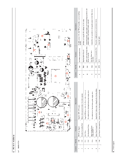
6. PCB DIAGRAM

6-1. MAIN PCB


                                                                                                                                                                  11


                                                                     12

                                                                                                                                                                                            13


                                              1
                                                                                                                                                                            10


                                                      2

                                                                                                                      9


                                                  5
                                                                                                                               6
                                                                 3                                  4                                                  7                           8


 Location   Part No.            Function                                              Description                     Location     Part No.            Function                                         Description

    1         CN2      PBA Power Supply                   Supplies 120V of AC power                                                                                         Supplies power to the Sub PBA and provides a communications
                                                                                                                          8         CN8       SUB PBA Connection Port
                                                                                                                                                                            function.
    2         CN1      Reactor Connection Port            Blocks noise generated when the motor operates.
                                                                                                                          9         IPM1      Washing Motor Drive IC        Switches and supplies the voltages for the motor.
    3         RY1      Main Relay                         Supplies PBA power when the Power button is pressed.
                                                                                                                                              Water Level And Temperature   Detects the laundry, water supply, and water draining operations and
                                                                                                                          10        CN7
    4         RY3      Washing Heater Relay               The switch for the Washing Heater power supply drive.                               Sensor Connector              detects whether each heater is working properly.

                       Steam Heater Relay                                                                                                     Door And Silver Nano
    5         RY4                                         The switch for the Steam Heater power supply drive.             11        CN4                                     Detects the door operations and supplies power for the Silver Nano.
                       (Only WF448***)                                                                                                        Connector

    6         CN5      Motor Power Supply Port            Supplies the 3-phase drive voltage for the Washing Motor.       12        CN3       Each Load Connection Port     The port to supply power for each electric device.

    7         CN6      Hole Sensor Connection Port        Detects whether the Washing Motor is working normally.          13        IC18      Ag IC                         Drives the Ag IC.


90 _ PCB Diagram
6-2. CONNECTOR AND RELAY PORT PART DETAILED MANUAL (MAIN PCB)


                                           CN3
                                          1. Door Lock Close                                                                                CN4
                                          2. Door Lock Open      6. Circulation Pump                                                       1. Door Switch      5. Empty Pin
                                          3. Drain Pump          7. Pre Valve                                                              2. Empty Pin        6. Empty Pin
                                          4. Steam Valve         8. Main Valve                                                             3. Door Switch      7. AG Sensor
                                          5. Bleach Valve        9. Hot Valve                                                              4. Empty Pin        8. AG Sensor


  CN2
 1. AC Power Port
 2. AC Power OFF Detection
                                                                                                                                                                                   CN7
    Sensor
                                                                                                                                                                                  1. Empty Pin
 3. Door Detection Sensor
    (LOCK, UNLOCK)                                                                                                                                                                2. Empty Pin
                                                                                                                                                                                  3. Empty Pin
                                                                                                                                                                                  4. Washing Water Temperature
                                                                                                                                                                                     Sensor
                                                                                                                                                                                  5. Ground
                                                                                                                                                                                  6. Washing Water Level Sensor
                                                                                                                                                                                  7. Washing Water Level Sensor
  CN1
 1. Reactor Connection Port
 2. Reactor Connection Port


                                                                                                                                                                                   CN8
                                                                                                                                                                                  1. Communications Port (Rx)
                                                                                                                                                                                  2. Communications Port (Tx)
  RY4 (Only WF448***)
                                                                                                                                                                                  3. Rest Signal Output
 1. Steam Heater Relay Switch
                                                                                                                                                                                  4. Ground
 2. Steam Heater Relay Switch
                                                                                                                                                                                  5. 5V
                                                                                                                                                                                  6. 15V


                                 RY1                            RY4                              CN5                        CN10                           CN6
                                1. Main Power Relay Switch     1. Washing Heater Relay Switch   1. Motor Power (U Phase)   1. AC OFF Check                1. 5V
                                2. Main Power Relay Switch     2. Washing Heater Relay Switch   2. Motor Power (V Phase)   2. Test Mode                   2. Hole Sensor Signal
                                                                                                3. Motor Power (W Phase)   3. 5V                          3. Hole Sensor Signal
                                                                                                                           4. Transmission Port           4. Ground
                                                                                                                           5. Ground
                                                                                                                           6. Input Port


                                                                                                                                                                                                 PCB Diagram _ 91
6-3. SUB PCB


                                                                            2
                                                                2


                   1
                                                                                                                                                                                       3
                                                                2

                                                                            2


                       4


                           Location        Part No.                   Function                                                   Description

                              1           LCD CN3          Main PBA Connection Port       Receives power from the Main PBA and provides a communications function.

                              2       LCD CN1 and so on.   LCD, Display Connection Port   Connects the LCD Board and the Graphics Board.

                              3          Graphic CN1       Power Connection Port          Connects power.

                              4              BZ1           Buzzer Circuit                 Generates sound when the Menu key is pressed, the Encoder operates and the menu is closed.


92 _ PCB Diagram
6-4. CONNECTOR PORT PART DETAILED MANUAL (SUB PCB)


                                                      CN4_GRAPHIC
                                                     1. Tub Light Drive Signal
                                                     2. Empty Pin
                                                     3. Ground


  CN1_LCD                                                    CN1_GRAPHIC
 1. Communications Port (Tx)                                1. CO
 2. Communications Port (Rx)                                2. Empty Pin
 3. Outputs the Reset Signal                                3. NO
 4. Ground                                                  4. Empty Pin
 5. 5V                                                      5. NC
 6. 15V


                                                                  PCB Diagram _ 93


◦ Jabse Service Manual Search 2024 ◦ Jabse PravopisonTap.bg ◦ Other service manual resources online : FixyaeServiceinfo