Service Manuals, User Guides, Schematic Diagrams or docs for : Samsung Washer WF448AAP_XAA Removal_and_Reassembly
<< Back | HomeMost service manuals and schematics are PDF files, so You will need Adobre Acrobat Reader to view : Acrobat Download Some of the files are DjVu format. Readers and resources available here : DjVu Resources
For the compressed files, most common are zip and rar. Please, extract files with Your favorite compression software ( WinZip, WinRAR ... ) before viewing. If a document has multiple parts, You should download all, before extracting.
Good luck. Repair on Your own risk. Make sure You know what You are doing.
Image preview - the first page of the document

>> Download Removal_and_Reassembly documenatation <<
Text preview - extract from the document
3. DISASSEMBLY AND REASSEMBLY

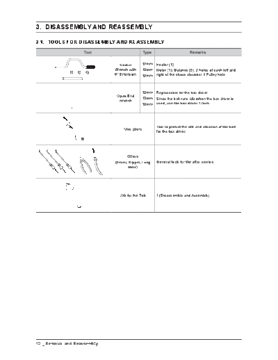
3-1. TOOLS FOR DISASSEMBLY AND REASSEMBLY
                    Tool                         Type                        Remarks


                                 Socket          10mm Heater (1)
                              Wrench with        13mm Motor (1), Balance (5), 2 holes of each left and
                              6" Extension       19mm right of the shock absorber 1 Pulley hole


                                                 10mm Replaceable for the box driver.
                               Open End
                                                 13mm Since the bolt runs idle when the box driver is
                                wrench
                                                 19mm used, use the box driver 17mm.


                                                         Tool to protect the idle and abrasion of the bolt
                                   Vice pliers
                                                         for the box driver.


                                     Others
                              (Driver, Nipper, Long      General tools for the after service.
                                      nose)


                                JIG for the Tub          1 (Disassemble and Assemble)


10 _ Removal and Reassembly
3-2. STANDARD DISASSEMBLY DRAWINGS
 This is a standard disassembly diagram and may differ from the actual product.
 Use this material as a reference when disassembling and reassembling the product.

         Part                          Figure                                      Description


                                                             1. Remove the two screws holding the Top Cover at
                                                                the back of the unit.


                                                             2. Remove the top-cover by lifting it up after pulling it
                                                                back about 15mm.
  ASSY COVER TOP


                        Noise filter        Water valve


                                                             3. With the top cover removed you will now have
                                                                access to service the Water pressure sensor, EMI
                                                                Noise Filter, Hot and Cold Water Valves, Steam
                                                                ASSY, Hose Draw ASSY, and Main PCB ASSY.


                                         Sensor pressure


                                                                                 Removal and Reassembly _ 11
       Part                   Figure                       Description


                                       1. Remove the 2 screws at the top of the ASSY-
                                          PANEL CONTROL.


                                       2. Hold the ASSY-PANEL CONTROL while pulling it
                                          upwards and release the hook to remove it.


   MAIN-PCB AND
  SUB-PCB PANEL


                                       3. Carefully disconnect the two wiring connectors by
                                          hand.


                                       4. Remove the 10 screws holding the PCB and
                                          release the hooks on both sides to remove the
                                          PCB for repair / replacement.


12 _ Removal and Reassembly
    Part      Figure                         Description
◦ Jabse Service Manual Search 2024 ◦ Jabse Pravopis ◦ onTap.bg ◦ Other service manual resources online : Fixya ◦ eServiceinfo