Service Manuals, User Guides, Schematic Diagrams or docs for : Sony Car Stereo Service Bulletin CAR0400
<< Back | HomeMost service manuals and schematics are PDF files, so You will need Adobre Acrobat Reader to view : Acrobat Download Some of the files are DjVu format. Readers and resources available here : DjVu Resources
For the compressed files, most common are zip and rar. Please, extract files with Your favorite compression software ( WinZip, WinRAR ... ) before viewing. If a document has multiple parts, You should download all, before extracting.
Good luck. Repair on Your own risk. Make sure You know what You are doing.
Image preview - the first page of the document

>> Download CAR0400 documenatation <<
Text preview - extract from the document
                                           CONFIDENTIAL                                                   CSA-14
Sony Service Company
National Technical Services                Service Bulletin
A Division of Sony Electronics Inc.
Park Ridge, New Jersey 07656               Car Stereo
Model:           CDX-91                                                                   No.       400
Subject: Pop Noise Prior To Start Of Audio.                                               Date: June 14, 1996


Symptom:
  (54)                  In some units after changing the disc, pop noise from the speakers may be heard
                        prior to the start of audio.


Solution:               If the customer complains of this problem follow the procedure shown below.

                             REF               DESCRIPTION                          PART NUMBER

                             C321      CAPACITOR ELECTROLYTIC                        1-128-426-11
                                              (47uF/16V)


                        Applicable Serial Numbers: 10001 to 15000

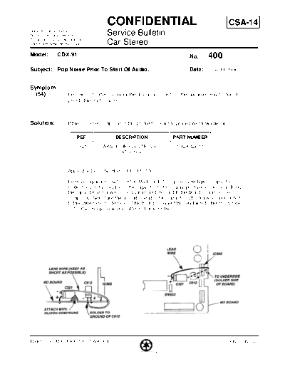
                        Remove capacitor C321 from the MD board. Using the same type of capacitor
                        solder the positive lead(+) of the capacitor to it's original positive (+) location. Bend
                        the capacitor as shown in the diagram and mount it to the board using silicone
                        compound. Next, take the ground(-) lead of the capacitor, attach a wire, and route it
                        to the underside (solderside) of the board. Connect this lead wire to the minus side (-
                        ) of C912. Keep the wire length short as possible.


Reference: M.E. FAX TX-USA96004                                                                           PRINTED IN USA

                                                        PRINTED ON RECYCLED PAPER
◦ Jabse Service Manual Search 2024 ◦ Jabse Pravopis ◦ onTap.bg ◦ Other service manual resources online : Fixya ◦ eServiceinfo