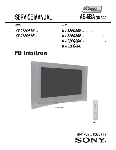
Service Manuals, User Guides, Schematic Diagrams or docs for : Sony SONY KV chassis KV-28FQ86E
<< Back | HomeMost service manuals and schematics are PDF files, so You will need Adobre Acrobat Reader to view : Acrobat Download Some of the files are DjVu format. Readers and resources available here : DjVu Resources
For the compressed files, most common are zip and rar. Please, extract files with Your favorite compression software ( WinZip, WinRAR ... ) before viewing. If a document has multiple parts, You should download all, before extracting.
Good luck. Repair on Your own risk. Make sure You know what You are doing.
Image preview - the first page of the document

>> Download KV-28FQ86E documenatation <<
Text preview - extract from the document
SERVICE MANUAL                                           AE-6BA CHASSIS
MODEL        COMMANDER   DEST   CHASSIS NO.     MODEL        COMMANDER   DEST     CHASSIS NO.


KV-28FQ86B   RM-945      FR     SCC-Q83T-A      KV-32FQ86B   RM-945      FR       SCC-Q83U-A


KV-28FQ86E   RM-945      ESP    SCC-Q81W-A      KV-32FQ86E   RM-945      ESP      SCC-Q81X-A


                                                KV-32FQ86K   RM-945      OIRT     SCC-Q82M-A


                                                KV-32FQ86U   RM-945      UK       SCC-Q84T-A


                                         KV-32FQ86


                                                                              RM-945


                                              -1-
                                                            TABLE OF CONTENTS
Section          Title                                                     Page     Section          Title                                             Page

                 Caution                            ....................   3        5. DIAGRAMS
                 Specifications                     ....................   4
                 Connectors                         ....................   6                  5-1.   Block Diagrams (1)         ....................   25
                 Self Diagnostic Software           ....................   7                         Block Diagrams (2)         ....................   26
                                                                                                     Block Diagrams (3)         ....................   27
1. GENERAL                                                                                           Block Diagrams (4)         ....................   28
                 Switching On the TV and                                                      5-2.   Circuit Board Location     ....................   28
                 Automatically Tuning         ....................         8                  5-3.   Schematic Diagrams and
                 Introducing and Using the Menu                                                      Printed Wiring Boards      ....................   28
                 System                       ....................         9                             * A Board Schematic    ....................   30
                 The Picture Adjustment Menu ....................          9                             * A Board PWB          ....................   33
                 The Sound Adjustment Menu ....................            10                            * B Board Schematic    ....................   35
                 PAP (Picture and Picture)    ....................         10                            * B Board PWB          ....................   37
                 Teletext                     ....................         11                            * D2 Board Schematic   ....................   38
                 Remote Control Configuration                                                            * D2 Board PWB         ....................   37
                 for VCR or DVD               ....................         11                            * F1 Board Schematic   ....................   39
                 Technical Specifications     ....................         12                            * F1 Board PWB         ....................   40
                 Lifting the TV Set           ....................         12                            * H1 Board Schematic   ....................   39
                 Troubleshooting              ....................         13                            * H1 Board PWB         ....................   40
                                                                                                         * VM Board Schematic   ....................   39
2. DISASSEMBLY                                                                                           * VM Board PWB         ....................   40
                                                                                                         * G Board Schematic    ....................   41
          2-1.   Rear Cover Removal            ....................        14                            * G Board PWB          ....................   40
          2-2.   Speaker Connector Disconnection................           14                            * C Board Schematic    ....................   42
          2-3.   Chassis Removal and Refitting ....................        14                            * C Board PWB          ....................   43
          2-4.   Service Position              ....................        15                            * J Board Schematic    ....................   44
          2-5.   G Board Removal               ....................        15                            * J Board PWB          ....................   43
          2-6.   D2 Board Removal              ....................        15                            * D Board Schematic    ....................   46
          2-7.   D Board Removal               ....................        15                            * D Board PWB          ....................   45
          2-8.   Picture Tube Removal          ....................        16
                 Bottom Plates                 ....................        17                 5-4.   Semiconductors             ....................   47
                                                                                              5-5.   IC Blocks                  ....................   49
3. SET-UP ADJUSTMENTS
                                                                                    6. EXPLODED VIEWS
          3-1.   Beam Landing                       ....................   18
          3-2.   Convergence                        ....................   19                 6-1.   Chassis                    ....................   51
          3-3.   Focus Adjustment                   ....................   21                 6-2.   Picture Tube               ....................   52
          3-4.   Screen (G2), White Balance         ....................   21
                                                                                    7. ELECTRICAL PARTS LIST                    ....................   53
 4. CIRCUIT ADJUSTMENTS

          4-1.   Electrical Adjustments             ....................   22                                   ATTENTION
          4-2.   Test Mode 2                        ....................   24
                                                                                    APRES AVOIR DECONNECTE LE CAP DE'LANODE,
                                                                                    COURT-CIRCUITER L'ANODE DU TUBE CATHODIQUE ET
                                CAUTION                                             CELUI DE L'ANODE DU CAP AU CHASSIS METALLIQUE DE
                                                                                    L'APPAREIL, OU AU COUCHE DE CARBONE PEINTE SUR LE
SHORT CIRCUIT THE ANODE OF THE PICTURE TUBE AND THE                                 TUBE CATHODIQUE OU AU BLINDAGE DU TUBE
ANODE CAP TO THE METAL CHASSIS, CRT SHIELD, OR THE                                  CATHODIQUE.
CARBON PAINTED ON THE CRT, AFTER REMOVAL OF THE                                                          ATTENTION !!
ANODE CAP.
                                                                                    AFIN D'EVITER TOUT RISQUE D'ELECTROCUTION
                               WARNING !!                                           PROVENANT D'UN CH
◦ Jabse Service Manual Search 2024 ◦ Jabse Pravopis ◦ onTap.bg ◦ Other service manual resources online : Fixya ◦ eServiceinfo